
Installation manual


Engineering - 44
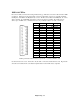
Pin Input Output Pin Input Output
1 Input 1 Output 1 2 Input 2 Output 1
3 Input 3 Output 1 4 Input 4 Output 1
5 Input 5 Output 1 6 Input 6 Output 1
7 Input 7 Output 1 8 Input 8 Output 1
9 Input 1 Output 2 10 Input 2 Output 2
11 Input 3 Output 2 12 Input 4 Output 2
13 Input 5 Output 2 14 Input 6 Output 2
15 Input 7 Output 2 16 Input 8 Output 2
17
Ground 18 Ground
19
5 Volts DC 20 12 Volts DC
CN 3
Pin Input Output Pin Input Output
1 Input 1 Output 3 2 Input 2 Output 3
3 Input 3 Output 3 4 Input 4 Output 3
5 Input 5 Output 3 6 Input 6 Output 3
7 Input 7 Output 3 8 Input 8 Output 3
9 Input 1 Output 4 10 Input 2 Output 4
11 Input 3 Output 4 12 Input 4 Output 4
13 Input 5 Output 4 14 Input 6 Output 4
15 Input 7 Output 4 16 Input 8 Output 4
17
Ground 18 Ground
19
5 Volts DC 20 12 Volts DC
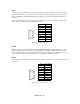
Routing lines for 8x4 Harness.
For example, if input 3 needed to be routed to output 3, then pin 3 on CN 3 should be shorted to either pin
17 or 18 on CN 3. Sometimes, it is desirable for an input to always be on. If an engineer wanted to wire a
bank of CD players into the 8x4 Switcher, he or she could simply short the appropriate digital output from
the SMARTCASTER to Ground using these connectors.
In addition, there are sockets for relays and other circuit modifications located above the terminal strips.
These can be used at will for making modifications.