
Installation manual


Engineering - 43
Theoretically, levels should now be the same for all inputs. However, if a channel through output 1 of the
Switcher needs to be checked, go to the main automation Screen of SMARTCASTER. The following
keystrokes route different inputs to the appropriate output:
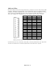
Keystrokes to route AMX Switcher Channels
Bank 1 Bank 2 Bank 3 Bank 4
Input 1 Alt-F1 Alt-F9 Shift-F5 Ctrl-F5
Input 2 Alt-F2 Alt-F10 Shift-F6 Ctrl-F6
Input 3 Alt-F3 Alt-F11 Shift-F7 Ctrl-F7
Input 4 Alt-F4 Alt-F12 Shift-F8 Ctrl-F8
Input 5 Alt-F5 Shift-F1 Shift-F9 Ctrl-F9
Input 6 Alt-F6 Shift-F2 Shift-F10 Ctrl-F10
Input 7 Alt-F7 Shift-F3 Shift-F11 Ctrl-F11
Input 8 Alt-F8 Shift-F4 Shift-F12 Ctrl-F12
Alt-A Cancel All Bank 1
Alt-B
Cancel All Bank 2
Alt-C
Cancel All Bank 3
Alt-D
Cancel All Bank 4
Alt-E
Cancel All Banks
As each input is turned on or off, the appropriate LED lights on the Channel Activity Meter located on the
front of the unit. Remember, if Setup has been told that SMARTCASTER Air output has been wired
through input 8, then this light is always on.
AMX 8x4 Harness Card (In Detail)
Sometimes it is necessary to make modifications to the Harness Card. Details provided from within this
section of the documentation should make this possible. However, if traces need to be cut, please contact
the SMARTS Support Staff to verify that no damage occurs.
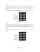
To each side of CN 1 and CN 3, are headers for connections. Connectors for these headers can be
obtained at any electronic supply house. (Contact SMARTS for ordering information.) These lines are
used to route inputs of the AMX Switcher to any of the four outputs. Each output uses eight digital output
lines from the SMARTCASTER - one for each audio input. To route an input on the AMX Switcher, the
appropriate digital line should be shorted to Ground.
CN 1