
Installation manual


Engineering - 41
Digital Inputs for Relay Closures
All relay connections to the 8x4 Switcher are made via the two terminal strips located at the corner of the
8x4 Harness Card. All connections should be made with dry contact closures. Do not place any voltage
supply in series with satellite relay closures!!!! The digital inputs used with the 8x4 Switcher are not
Opto-Isolated, and will be seriously damaged if a power supply is placed in series with the relay closures
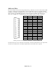
from the satellite receiver! A description of each terminal is shown below:
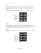
Terminal Strip Description of AMX 8x4 Harness
1
Digital Input 1 2 Digital Input 2
3
Digital Input 3 4 Digital Input 4
5
Digital Input 5 6 Digital Input 6
7
Digital Input 7 8 Digital Input 8
9
Digital Input 9 10 Digital Input 10
11
Digital Input 11 12 Digital Input 12
13
Digital Input 13 14 Digital Input 14
15
Digital Input 15 16 Digital Input 16
17
Ground 18 Ground
19
5 Volts DC 20 Strobe N/A
To connect a relay closure to the AMX Harness, first ‘bus’ together one side of all relay closures that will
be used from all satellite receivers. (Unlike other Switchers, the AMX can distinguish which closures are
valid through software.) Connect these Grounds via either terminal 17 or 18. Next, connect the other
side of each relay to a digital input terminal. Try to group relays from the same Network together.