
Installation manual

Engineering - 36
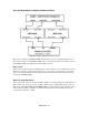
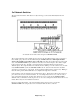
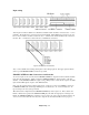
5x1 wiring to prevent closures being sensed by SMARTCASTER from Networks not on the air.
In the example above, there are three Networks wired to the 5x1 Switcher, and all have relay closures.
Pins 30-37 of the 37 pin connector, (Digital Input Low’s), are connected to the GND connection on the
5x1 Switcher. Next, each satellite receiver has one side of all of its relays bussed together, and connected
to its control line on the 5x1 Switcher. Finally, each specific relay is then wired into a specific Digital
Input High on the 37 pin connector. In this example, the first satellite receiver has a relay wired as
Function 0 on the SMARTCASTER, the second satellite receiver has a relay wired to Function 1, and the
third satellite receiver has a relay wired to Function 2. (For information on Functions and Local Breaks,
refer to CONTROL WIRING in this engineering manual.) Note: No external 12 Volt supply is needed
for the satellite receiver relays! The 5x1 Switcher provides the 12V internally.
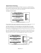
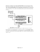
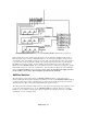
AMX 8x4 Switcher
The 8x4 Switcher provides many features to SMARTCASTER automation - giving it the power to
perform multi-Network automation. With the 8x4 Switcher, not only can the SMARTCASTER handle up
to 8 Network feeds for recording or playback purposes, but it can also handle 16 relay closures from the
different Networks. (More can be added with an additional expansion board.)
The wiring of the 8x4 is relatively simple. There are four outputs and eight inputs. Two outputs are used
to route any of the eight inputs to air or to the SMARTCASTER record inputs. There are no routing
limitations. It is possible to route an input to all four outputs at the same time if necessary. The AMX
8x4 Switcher is a very versatile product.