
Installation manual

Engineering - 35
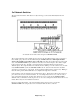
5x1 Network Switcher
The 5x1 Network Switcher, while based on relay technology, is wired a bit differently than the 2x1
Switcher.
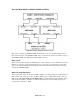
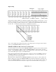
5x1 Switcher shown with control wiring from SMARTCASTER.
The top horizontal strip is the normally closed position for the five different inputs. The second strip is
the normally open position for the five different inputs. In almost all cases, audio inputs should be
wired to the normally open positions, (the second strip). The first strip should only be used in special
cases. The SMARTCASTER , upon command, routes any one of the five inputs to the common output
located on the bottom strip. All audio sources that must be switched should be wired into the five
different inputs. The output should be wired directly into the satellite pot on the control board. (As with
most SMARTCASTER systems, the SMARTCASTER ‘On Air’ audio from the hard drive should be
wired into a second input pot on the board. Levels can then be matched at the control board.) Muting of
Networks during local commercial Breaks is accomplished through the 5x1 Switcher.
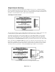
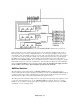
Control wiring for the 5x1 Switcher is shown in the figure above. The first five relays located on the 37
pin connector are used to control the Switcher. If , for example, Network 2 is to be on the air, relay 1,
(pins 4 & 5), latch and hold. If, at a later time, Network 1 is to be on the air, the SMARTCASTER
unlatches relay 1, and latches in relay 0, (pins 1 & 2). Of course, during times that the Networks are to be
muted, all five relays are in an unlatched condition.
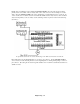
Like the 2x1 Network Switcher, some external wiring must be done in order to prevent the
SMARTCASTER from seeing closures from one Network while another is on the air.