
Installation manual

Engineering - 33
Simple Network Switching
There are several types of Network switching. The simplest version is a 2 in, 1 out Network Switcher
based on a latching relay circuit. The next step up is a 5 in, 1 out Switcher, also based on relays. Finally,
there is the 8 in, 4 out solid state Switcher. This section explains both the 2x1 and the 5x1 Switcher. For
information on the 8x4 Switcher, refer to a later section in this manual.
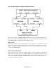
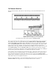
2x1 Simple Network Switcher
2x1 Simple Network Switcher.
The 2x1 Network Switcher is used for simple Network switching needs. For example, a station may want
to switch between a typical satellite music Network to a news service at the top of the hour.
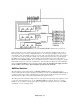
To install, just run audio lines for the primary satellite service, (Ex: Music Satellite), into the primary
audio source, (Terminals 5,6,7,8). Connect the audio lines of the secondary news service, (Ex: News
Feed), into the secondary audio source, (again, terminals 5,6,7,8). Finally, run a line from the output to
the muting relays of the SMARTCASTER. (On the 37- pin connector, these are 3:L+ 6:L- 9:R+ 22:R-)
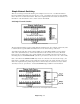
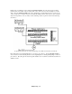
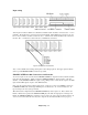
Next, control lines from SMARTCASTER relays need to be connected to the vertical control strip. (See
figure below.) Normally, relay 4 is used to latch the secondary input to the output, and relay 5 is used to
release the output back to the primary input. However, if these relays are used, there are ways to utilize
other relays on the 37- pin connector. Contact the SMARTS Support Staff for more information.
Control and Audio Lines wired to 2x1 Simple Network Switcher