
Installation manual

Engineering - 31
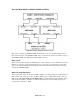
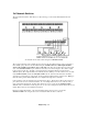
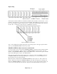
dBX 1024 FOR SIMULTANEOUS STEREO SYSTEM
dBX 1024 wiring for Simultaneous Stereo System.
With a stereo, simultaneous SMARTCASTER, two dBX units are needed. One dBX matches both the
Input and Air channels of the SMARTCASTER. The second unit simply matches the Audition output of
the SMARTCASTER. (The XLR Input to RCA Output is left free.)
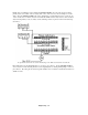
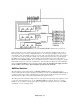
Pin 1 Switch
This switch internally disconnects the XLR Input pin 1, (both channels), from the 1024 Chassis Ground to
eliminate any Ground loop hum problems that may arise. If necessary, an internal jumper on the 1024
can be set to isolate the dBX Circuit Ground from the Chassis Ground if Ground loop hum problems are
caused by the SMARTCASTER.
Buffer Mode On/Off Switch
This rear panel slide switch sets the unit as a Buffer Amplifier for changing unbalanced +4dB signals into
balanced form. This switch selects either the RCA (-10dBV) inputs or XLR (+4dBu) inputs to drive the
XLR outputs. The switch should be in the OFF position, so that the XLR inputs drive the RCA outputs,
(with 11.8dB of attenuation; adjustable +/- 10dB), and the RCA inputs drive the XLR outputs, (with
11.8dB of gain, adjustable +/- 10dB).