
Installation manual
Engineering - 24
the Network. In addition, any Verification Logs can be retrieved from the units. If an existing unit is
being upgraded, please contact our Support Department in order to install the card and Lantastic software.
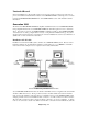
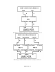
SmartSwitch Node
This computer node can handle any Network switching for multiple radio stations throughout the
Network. Audio can be routed for Unattended Records or live air feeds to virtually any point at the
installation site. In addition, transponder switching can be accomplished via relay closures. Please
contact the Support Department for the latest, up-to-date information on this product.
dBX 140 Impedance Matching Boxes
The dBX Option provides two important functions for proper SMARTCASTER operation. First, the unit
“compands” or smashes the audio entering the computer, and reduces the dynamic range at a ratio of
about 2 to 1. The encoder of the dBX performs this operation, while the decoder restores the audio from
the computer back to its original dynamic range.
Second, the dBX unit(s) provides a convenient way to match impedance from the high impedance,
unbalanced inputs/outputs of the SMARTCASTER to the standard 600 ohm broadcast circuitry.
In cases where the SMARTCASTER has stereo Simultaneous Playback and Record, two dBX units are
needed. This is because a Simultaneous unit has two outputs - “Audition” and “Air.” (Thus, one can
listen to a commercial just Recorded via Audition while other spots are going over the air via the Air
output.) With two stereo outputs, two stereo dBX decoders are needed. As a result, the second dBX unit
is just used for decoding only.
Mounting
The dBX unit(s) may be rack mounted using the mounting kit that is included, or it may simply be set in
any convenient location near the SMARTCASTER. (Refer to the dBX manual for instructions on the
rack mounting kit.) Note however that since the SMARTCASTER connections to the dBX unit are
unbalanced, the leads MUST BE AS SHORT AS POSSIBLE! Please take care that the unit is not near
any sources of RF that might interfere with its operation.
Connections
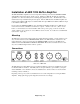
The plugs used with the dBX units are connected using the stereo “tip-ring-sleeve” type 1/4 inch plug. Do
not use the monaural version of this plug that only has a tip and a sleeve connection! (This plug is
the secret to proper impedance matching.)
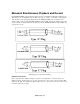
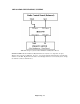
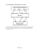
Diagrams of the connections between the control board, dBX(s), and the SMARTCASTER are shown in
the following figures. On the back of the dBX units are four sets of A and B channel connections labeled
“From Console,” “To Console,” “From Tape Rec.,” and “To Tape Rec.” Simply make the connections as
shown below with the correct type of 1/4” plug. A diagram for plug-types is shown following the dBX
wiring diagrams. For example, connection should be made between From Console and the output of the
control board with a “Type A” plug.