
Installation manual


Engineering - 18
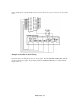
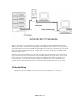
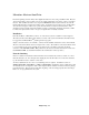
PCL 720 CARD (TTL I/O CARD)
Diagram of digital I/O card for CD control.
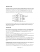
Next, take each individual control line from the Breakout cards and connect it to “Control In” of the
appropriate CD deck.
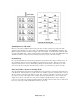
If one of the cables has come loose from the Breakout card, refer to the table below for connection
information. All shields of the control cable should be connected to either pin 17 or 18 on the Breakout
card, (GND). The tips should be connected as follows:
Deck 1 - 16 : Pins 1 - 16 of the first card.
Deck 17-32 : Pins 1-16 of second card.
Comm Cable Between CD Server and SMARTCASTER
An RS-232 cable must be connected between the CD Server and the main SMARTCASTER unit. This
allows the SMARTCASTER to “talk” to the CD Server in order to set up, play, and stop the CD decks.
A communications cable, (Comm Cable), is provided by SMARTS. One end should be connected to Com
1 of the CD Server, (9 pin male connection). The other end should be connected to Com 3 of the
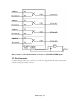
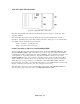
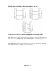
SMARTCASTER main unit. Com 3 is also a 9 pin male connection. In the event the current cable is
somehow damaged, it is simple to wire a new one. The table on the next page provides a schematic for
wiring either 9 pin or 25 pin connectors to a Comm Cable. DCD, DTR, DSR, and CTS must all be
jumpered together. Rx and Tx on one end of the cable must be crossed with Rx and Tx on the other end.
(In other words, Rx is connected to Tx of the other computer, and vice versa.)
This same cable is also used to connect the Remote Record unit with the main SMARTCASTER. For
more information, please refer to the section on COMMUNICATIONS CABLE.