
Installation manual


Engineering - 17
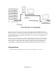
Summing Box for CD Audio
Please try to keep these unbalanced lines away from AC power lines as much as possible. The audio
output from the summing box is then routed to the unbalanced inputs of the dBX Buffer Amplifier. The
balanced outputs are then connected to an input on the control board. Level adjustments for the CD audio
are made at the Buffer Amp. (If this system contains an 8x4 Switcher, the output of the dBX Buffer Amp
should be connected to an input on the 8x4 Switcher instead of a input on the control board.)
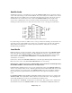
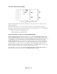
Ground Strap
It is very important that the commercial type CD players be Grounded to the chassis of the CD server. If
this common Ground is not present, the CD players cannot function correctly. Please wire a Ground
strap between the chassis of every commercial type CD player and the chassis of the CD server. (The
screw next to the fan on the back of the CD server provides a very convenient tie point for the strap.)
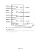
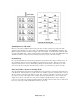
CD Control Lines - Pioneer Consumer Decks
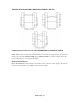
Two 20- pin Breakout boards with screw terminals have been provided for connection from the CD server
to the CD decks. The first board, for possible decks 1-16, should be connected, via ribbon cable, to the top
20- pin connector on the back of the CD server unit. The second board should be connected to the top 20-
pin connector located on the surface of the controller card located inside the unit. (To access this card,
simply remove the top of the CD server. The card is standing vertically inside the chassis. With the
power off, remove this card, and plug the ribbon cable into the TOP connector, CN3) The second board is
be used to control any possible decks numbered between 17 and 32.