New Solution Series NSK3480 User’s Manual Manuel de l’utilisateur Anwenderhandbuch Manuale per l’operatore Manual del usuario পᡅ䂀ᯢ
At Antec, we continually refine and improve our products to ensure the highest quality. It’s possible that your new case will differ slightly from the descriptions in this manual. This isn’t a problem; it’s simply an improvement. As of the date of publication, all features, descriptions, and illustrations in this manual are correct. Disclaimer This manual is intended only as a guide for Antec’s Computer Enclosures.
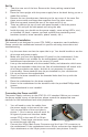
Set Up 1. 2. 3. 4. 5. 6. Take the case out of the box. Remove the foam packing material and plastic bag. Place the case upright with the power supply fan at the back facing you on a stable flat surface. Remove the two thumbscrews fastening to the top cover of the case. Set these screws aside and keep them separate from the other screws. Slide the top panel toward the rear of the case and lift it up. There are tabs at the top of each side panel located in front the power supply.
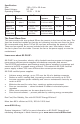
3. 4. 5. 6. Picture 2 Picture 3 Note: the detachable 4-pin section cannot be used in place of a 4-pin +12V connector. Connect the Reset switch (labeled RESET SW) to the motherboard at the RST connector. Polarity (positive and negative) does not matter for switches. For 24-pin For 20-pin motherboards Power Switch (labeled POWER SW) connects to the motherboards PWR connector on the motherboard. Power LED (labeled POWER LED) connector is located behind the Reset connector.
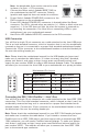
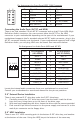
Pin Assignment for Front Panel IEEE 1394 Connector 1 2 9 10 Pin Signal Names Pin Signal Names 1 TPA+ 2 TPA– 3 Ground 4 Ground 5 TPB+ 6 TPB– 7 +12V (Fused) 8 +12V (Fused) 9 Key (No Pin) 10 Ground Connecting the Audio Ports (AC’97 and HDA) There is an Intel standard 10-pin AC’97 connector and an Intel 10-pin HDA (High Definition Audio) connector; you can connect either the AC’97 or the HDA connector to your motherboard depending on the spec of the motherboard.
result in being unable to use the 4th PCI slot depending on the length of the card used. Both HDD trays use soft silicone grommets to mount the HDD. 1. 2. 3. 4. 5. Remove the screw fastening the HDD tray to the case and slide the tray out of the case. Mount the hard drive into the drive tray through the bottom silicone grommets with the special screws provided. Note: Don’t over-tighten the screws. Over-tightening the screws will reduce the vibration and noise-dampening ability of the silicone grommets.
Specifications Size: Rated Voltage: Operating Voltage: Speed Input Current 120 x 120 x 25.4 mm DC 12V 10.2V ~ 13.8V Air Flow Static Pressure Acoustical Noise Input Power High 2000 RPM 0.24A (Max.) 2.24 m³ / min (79 CFM) 2.54 mm-H2O (0.10 inch-H2O) 30 dBA 2.9 W Medium 1600 RPM 0.2A 1.59 m³ / min (56 CFM) 1.53 mm-H2O (0.06 inch-H2O) 28 dBA 2.4 W Low 1200 RPM 0.13A 1.1 m³ / min (39 CFM) 0.92 mm-H2O (0.04 inch-H2O) 25 dBA 1.
Antec, Inc. 47900 Fremont Blvd. Fremont, CA 94538 USA tel: 510-770-1200 fax: 510-770-1288 Antec Europe B.V. Stuttgartstraat 12 3047 AS Rotterdam The Netherlands tel: +31 (0) 10 462-2060 fax: +31 (0) 10 437-1752 Customer Support: US & Canada 1-800-22ANTEC customersupport@antec.com Europe +31 (0) 10 462-2060 europe.techsupport@antec.com www.antec.com © Copyright 2007 Antec, Inc. All rights reserved. All trademarks are the property of their respective owners.