Twelve Hundred User’s Manual Manuel de l’utilisateur Anwenderhandbuch Manuale per l’operatore Manual del usuario পᡅ䂀ᯢ Ё᭛Փ⫼ݞ
At Antec, we continually refine and improve our products to ensure the highest quality. As such, your new case may differ slightly from the description in this manual. This isn’t a problem; it’s simply an improvement. As of the date of publication, all features, descriptions, and illustrations in this manual are correct. Disclaimer This manual is intended only as a guide for Antec’s Computer Enclosures.
Installing the Motherboard This manual is not designed to cover CPU, RAM, or expansion card installation. Please consult the motherboard manual for specific mounting instructions and troubleshooting. Before proceeding, check the manual for your CPU cooler to find out if there are steps you must do before installing the motherboard. 1. Lay the case down so that the open side is up. 2. Make sure you have the appropriate I/O panel for the motherboard.
Installing the Power Supply 1. With the case upright, place the power supply on the four silicone pads on the bottom of the case. Note: Power supplies with fans on the bottom of the power supply will need to be mounted so that the fan is facing the top of the case. Twelve Hundred provides mounting holes for power supplies with standard mounting layouts to be installed upside up or upside down. 2. Push the power supply to the back of the case and align the mounting holes. 3.
Connecting the Audio Ports (AC’97 and HDA) There is an Intel® standard 10-pin AC’97 connector and an Intel® 10-pin HDA (High Definition Audio) connector. You can connect either the AC’97 or the HDA connector, but not both at once, to your motherboard depending on the spec of the motherboard.
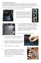
External 5.25” Device Installation Note: The HDD cages each occupy three consecutive drive bays, and will block installation of larger devices such as optical drives, so please plan ahead before installing your drives. 1. 2. 3. Remove both side panels per the instructions in Setting Up. Remove the screws fastening the appropriate metal drive bay cover(s) to the sides of the case. Remove the cover(s). 4. If necessary, please remove the HDD cage that is preinstalled in the bay. 5. Slide the 5.
External 3.5” Drive Installation 1. 2. 3. 4. Remove both side panels per the instructions in Setting Up. Remove the drive bay cover from the drive bay you wish to install an external 3.5” drive into. Install your external 3.5” device into the adapter. Slide the drive adapter/device assembly into the bay. 5. 6. Screw the adapter to the drive cage. Mount the faceplate and secure it with screws. Cable Management There is a cable management compartment between the motherboard and right side panel.
200mm Fan Specifications: Size: Rated Voltage: Operating Voltage: 200 x 30mm three-speed fan 12V DC 10.8V ~ 13.2 V Speed Input Current Air Flow Static Pressure Acoustical Noise Input Power High 800 RPM 0.3A 3.80 m³ / min (134 CFM) 0.69mm-H2O (0.027 inch-H2O) 30 dBA 3.6 W Medium 600 RPM 0.17A 3.07 m³ / min (108 CFM) 0.40mm-H2O (0.016 inch-H2O) 27 dBA 2.04 W Low 400 RPM 0.08A 2.34 m³ / min (82 CFM) 0.2mm-H2O (0.008 inch-H2O) 24 dBA 1.
The Optional Fans There are two optional 120mm fan mounts—the side fan (on the left side panel) and the middle fan (at the rear end of the HDD cage). We recommend using Antec 120mm TriCool™ fans and setting the speed to Low. These two fans should be installed so that the air is blowing into the case. The Side Fan — the side fan opening is there to enhance graphics card cooling. Just snap a fan into the bracket on the side panel so that it blows air into the case.
Side Air Filter – There is a filter located in the side fan bracket. It is located on the inside of the side panel, so you must open the side panel to access it. Remove the filter by sliding it out of the bracket. From time to time it will be necessary to wash the installed air filters. Not washing the air filter will result in high system temperatures and possible stability problems. We recommend checking the air filter at least once a month initially.
Antec, Inc. 47900 Fremont Blvd. Fremont, CA 94538 USA tel: 510-770-1200 fax: 510-770-1288 Antec Europe B.V. Stuttgartstraat 12 3047 AS Rotterdam The Netherlands tel: +31 (0) 10 462-2060 fax: +31 (0) 10 437-1752 Customer Support: US & Canada 1-800-22ANTEC customersupport@antec.com Europe +31 (0) 10 462-2060 europe.techsupport@antec.com www.antec.com © Copyright 2008 Antec, Inc. All rights reserved. All trademarks are the property of their respective owners.