
User Manual


Antaira Technologies - Industrial Ethernet Switches
LNX-C500G Series User Manual V1.1
5
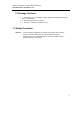
2.4 LED Indicators
There are LED light indicators located on the front panel of the industrial Ethernet switch that
display the power status and network status. Each LED indicator has a different color and has
its own specific meaning, see below in Table 2.1.
LED Color Description
Power
Green
On Power input is active
Off Power input is inactive
LAN Port 1 ~ 5
(Left LED)
Green
On Connected to network, 1000Mbps
Flashing
Networking is active
Off Not connected to network
LAN Port 1 ~ 5
(Right LED)
Green
On Connected to network, 10Mbps/100Mbps
Flashing Networking is active
Off Not connected to network
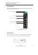
2.5 Ethernet Ports
RJ-45 Ports
RJ-45 Ports (Auto MDI/MDIX): The RJ-45 ports (LAN 1~5) are auto-sensing for
10/100/1000Base-T, or 100Base-Tx devices connections. Auto MDI/MDIX means that the switch
can connect to another switch or workstation without changing the straight-through or crossover
cabling. See the figures shown below for straight-through and crossover cabling schematics.
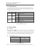
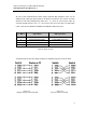
RJ-45 Pin Assignments (Table 2.2)
Pin Number Assignment
1 Rx+
2 Rx-
3 Tx+
6 Tx-
Note
: The “+” and “-” signs represent the polarity of the wires that make up each wire pair.
Table 2.1
LED Indicators for LNX-C500G Series
Table 2.2
RJ45 Pin Assignments