
User Manual

5
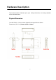
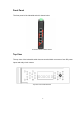
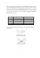
LED Indicators
The diagnostic LEDs located on the front panel of the Industrial switch provide real-time
information of the system and optional status. The following table provides the
description of the LED status.
LED
Color Description
P1 Green
On Power input 1 is active
Off Power input 1 is inactive
P2 Green
On Power input 2 is active
Off Power input 2 is inactive
Fault Red
On Power input 1 or 2 has failed, port link is inactive
Off
Power input 1 and 2 are both functional, or no power
inputs/port’s link is active/port alarm is disabled
LAN Port 1 ~ 5
Green
(Upper
LED)
On Connected to network
Flashing Networking is active
Off Not connected to network
Green
(Lower
LED)
On Connected to network, 1000Mbps
Off Not connected to network
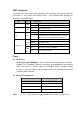
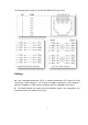
Ports
RJ-45 Ports
RJ-45 Ports (Auto MDI/MDIX): The RJ-45 ports are auto-sensing for 10Base-T,
100Base-TX or 1000Base-T devices connections. Auto MDI/MDIX means that the
switch can connect to another switch or workstation without changing straight
through or crossover cabling. See the figures below for a straight through and
crossover cable schematic.
RJ-45 Pin Assignments
Pin Number Assignment
1 Rx+
2 Rx-
3 Tx+
6 Tx-
Note
“+” and “-” signs represent the polarity of the wires that make up each wire pair.