
User Manual

Antaira Technologies - Industrial Ethernet Switches
LNX-1002G-10G-SFP User Manual V1.1
8
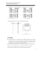
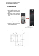
2.7 Wiring the Power Inputs
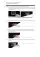
Please follow the below steps to insert the power wire.
1. Insert the positive and negative wires into the PWR1 (V1+, V1-) and PWR2 (V2+, V2-) contacts
on the terminal block connector as shown below in Figure 2.12.
2. Tighten the wire-clamp screws to prevent the wires from loosening, as shown below in Figure
2.13
*Note
Only use copper conductors, 60/75°C, tighten to 5 lbs.
The wire gauge for the terminal block should range between 18~20 AWG.
2.8 Wiring the Fault Alarm Contact
The fault alarm contact is in the
middle of the terminal block
connector as the picture shows
in Figure 2.14. By inserting the
wires, it will detect the fault
status including power failure or
port link failure (managed
industrial switch only) and form
a normally open circuit.
*Note
The wire gauge for the terminal block should range between 12 ~ 24 AWG.
If only using one power source, jumper Pin 1 to Pin 5 and Pin 2 to Pin 6 to
eliminate power fault alarm.
Figure 2.13 - Power Terminal Block
Figure 2.12 - Power Terminal Block
Figure 2.14
Wiring the Fault Alarm Contact