
User Manual


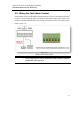

Table Of Contents
Antaira Technologies - Industrial Ethernet Switches
LNX-1002C-SFP Series User Manual V1.2
12
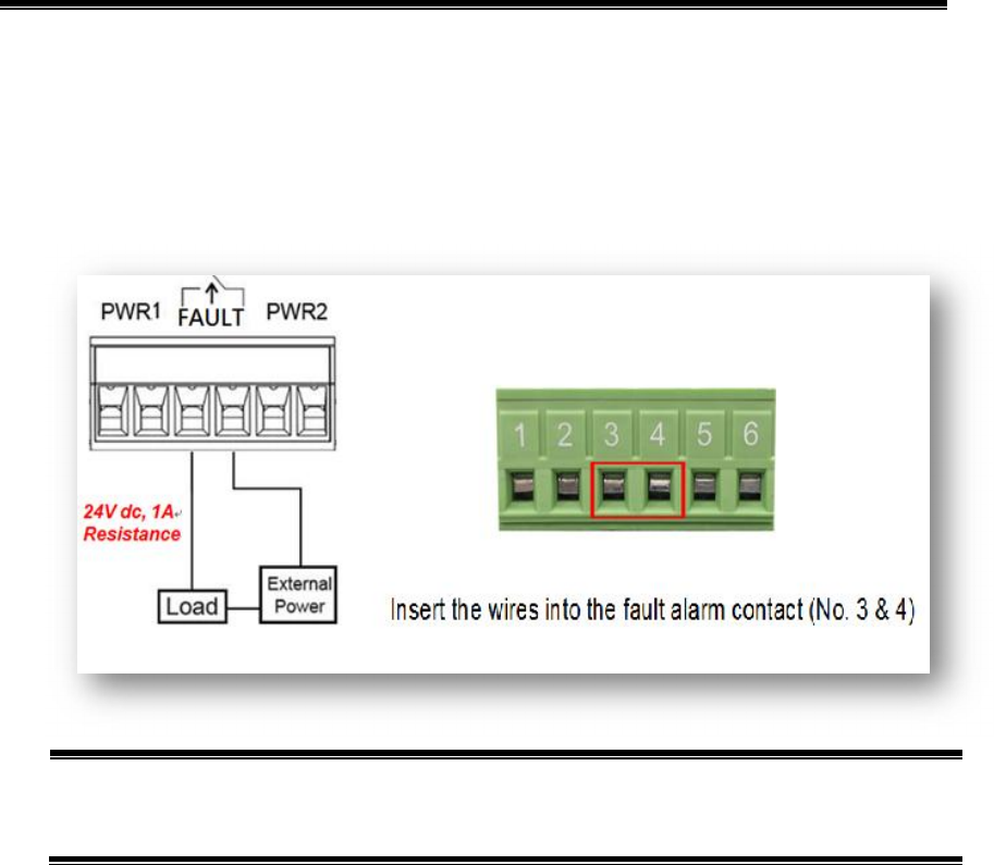
2.8 Wiring the Fault Alarm Contact
The fault alarm contact is in the middle of the terminal block connector as the picture shows below
in Figure 2.16. By inserting the wires, it will detect the fault status including power failure or port
link failure (managed industrial switch only) and form a normal open circuit. An example is shown
below in Figure 2.16.
**Note:
The wire gauge for the terminal block should range between 12 ~ 24 AWG.
If only using one power source, jumper Pin 1 to Pin 5 and Pin 2 to Pin 6 to
eliminate the power fault alarm.
Figure 2.16
Wiring the Fault Alarm Contact