
User Manual
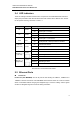
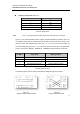
Table Of Contents
Antaira Industrial Ethernet Switches
LNX-0501G-SFP Series User Manual V1.2
6
RJ-45 Pin Assignments (Table 2.2)
Pin Number Assignment
1 Rx+
2 Rx-
3 Tx+
6 Tx-
All ports on this industrial Ethernet switch support automatic MDI/MDI-X operation. Users can
use straight-through cables (see figure below) for all network connections to PCs, servers, other
switches or hubs. With straight-through cable, pins 1, 2, 3, and 6, at one end of the cable, are
connected straight through to pins 1, 2, 3 and 6 at the other end of the cable. The table below
(Table 2.3) shows the 10BASE-T, 100BASE-TX, 1000BASE-TX MDI and MDI-X port pin outs.
Pin MDI-X Signal Name MDI Signal Name
1 Receive Data plus (RD+) Transmit Data plus (TD+)
2 Receive Data minus (RD-) Transmit Data minus (TD-)
3 Transmit Data plus (TD+) Receive Data plus (RD+)
6 Transmit Data minus (TD-) Receive Data minus (RD-)
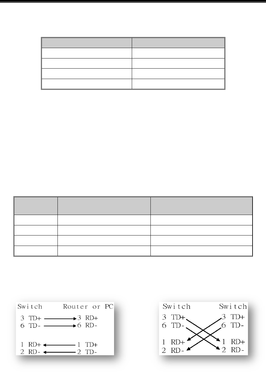
The following figures show the cabling schematics for straight-through and crossover.
Figure 2.4 Figure 2.5
Straight-Through Cable Schematic Crossover Cable Schematic
Note
“+” and “-” signs represent the polarity of the wires that make up each wire pair.
Table 2.2
RJ45 Pin Assignments
Table 2.3
Ethernet Signal Pin Outs