
User Manual

6
Antaira Technologies - Industrial Ethernet Switches
LMX-0800 Series Hardware Manual V1.3
2.4
LED Indicators
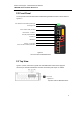
There are LED light indicators located on the front panel of the industrial Ethernet switch that
display the power status and network status. Each LED indicator has a different color and
has its own specific meaning, see below in Table 2.1.
LED Color Description
P1
Green
On Power input 1 is active
Off Power input 1 is inactive
P2
Green
On Power input 2 is active
Off Power input 2 is inactive
Fault
Red
On Fault has been triggered by a configured event (ex.
Port 7 link broken)
Off
Power input 1 and 2 are both functional, or no power,
inputs/ports link is active/port alarm is disabled
Owner
Green
On ERPS Owner Mode (Ring Master) is ready
Off
ERPS Owner Mode is not active
Ring
Green
On Ring Network is active
Off
Ring Network is not active
LAN Port 1 ~ 8
(Left LED)
Green
On Connected to network, 10/100Mbps
Flashing
Networking is active
Off Not connected to network
Table 2.1 - LED Indicators for LMX-0800 Series
Caution: "P1" is the abbreviation for "Power ", “P2” is for “Power 2”, “LNK” is for “Link”, and "ACT" is for
"Activity".
2.5
Reset Button
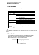
There is a ‘Reset’ button located on the front panel of the industrial Ethernet switch that helps
users to reboot, restore default, or save running configurations by pressing the button for
different seconds. Please refer to Table 2.2 for the timing and function.
Seconds Function
1
Save running configuration to USB
4-6 Reboot the switch
7 or more Restore factory default
Table 2.2 – Reset Button Functions