
Installation guide


4
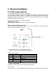
2. Physical Installation
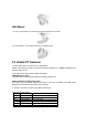
2.1 Dome Type Cameras
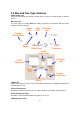
1. RJ45 LAN socket: Connect to PC or Hub/Switch.
For connections to 10Base-T Ethernet or 100Base-TX Fast Ethernet cabling. This Ethernet
port built N-Way protocol can detect or negotiate the transmission speed of the network
automatically. Please use Category 5 cable to connect the Network Camera to a 100Mbps
Fast Ethernet network switch or hub.
In the LAN socket, there are two LEDs embedded:
LAN LED (green color)
This LED will be flashing while network accessing via Ethernet.
Power or Wireless LED (orange color)
This LED is used to indicate whether DC power is on or not. In addition, this LED will be flashing
while the wireless accessing of the Camera.
2. RS-485: Connect to a local keyboard controller.
DI/ DO: Connect to sensor in and alarm out devices
Cable for I/O connectors:
Name Cable Color Function
12VDC Brown/White DC 12V (50mA maximum)
GND Blue/White GND
D+ Purple/White RS485 data +
D- Gray RS485 data -
DI Green/White Digital signal input
DO Orange/White Digital signal (alarm) output
3. Factory Default Reset
This button is used to restore the all factory default settings.
4. DC-in Jack
The input power is 12VDC. Note that supply the power to the Network Camera with the
RJ45
RS485 &
DI/DO
12V DC in
MIC in
Line out
Factory
Default Reset