H.264 Mega-Pixel / Multi-Profile Network Cameras Quick Start Guide 2009 Nov.
Table of Contents 1. System Requirements ......................................................................................................... 3 2. Physical Installation............................................................................................................ 4 2.1 Dome Type Cameras........................................................................................... 4 2.1.1 Indoor Dome Camera Installation ................................................................. 5 2.1.
About multi-profile Multi-profile stands for simultaneously video streams. These Network Cameras can generate H.264, MPEG4 and MJPEG streaming simultaneously to different clients. Moreover, the resolution can be different from one client to another. This state-of-art design is considerable to fit in various network environments. Before Installation Before installation, please be sure to read this quick installation guide and user’s manual carefully to complete machine installation. 1.
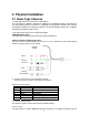
2. Physical Installation 2.1 Dome Type Cameras 1. RJ45 LAN socket: Connect to PC or Hub/Switch. For connections to 10Base-T Ethernet or 100Base-TX Fast Ethernet cabling. This Ethernet port built N-Way protocol can detect or negotiate the transmission speed of the network automatically. Please use Category 5 cable to connect the Network Camera to a 100Mbps Fast Ethernet network switch or hub.
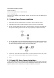
power adapter included in package. 5. MIC in (audio in) Connect a microphone to the network camera. 6. Line out (audio out) Connect a loud speaker to the network camera. This function is for voice alerting and two-way audio. 2.1.1 Indoor Dome Camera Installation 1. Please select the most suitable position on the wall or ceiling to install the camera. 2. Rotate the dome housing counterclockwise to remove it from the mounting base. 3.
2. Set the mounting base onto the wall or ceiling and center it over the mounting hole, using the supplied four retaining screws to secure the main body. 3. Set the proper image by moving the camera body (some model may limit the PCB board to180°rotational adjustment) and set the focus by turning the lens to the left or right direction. 4. When the camera focus adjustment has been completed, use the provided L-wrench to fasten the tamper-resistant housing to the main body. 5.
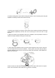
. Done 2.2 P/T Camera Audio Output Jack Antenna Connector DC Power Jack Audio Output Jack It allows this device to output audio or alerting sound. LAN Socket Factory Default Reset DC Power Jack The input power is 12VDC. Note that supply the power to the Camera with the power adapter included in package. Antenna Connector (wireless model only) User can attach the included wireless antenna to this connector (SMA type) or use another high-gain antenna to get higher performance.
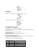
Wall Mount 1. Fix the L-type bracket to the wall using two holly wall anchors and screws 2. Fix the camera to L-type bracket with the two supplied screws 2.3 Vandal PT Cameras 1. RJ45 LAN socket: Connect to PC or Hub/Switch. Please use Category 5 cable to connect the Network Camera to a 100Mbps Fast Ethernet network switch or hub. In the LAN socket, there are two LEDs embedded: LAN LED (green color) This LED will be flashing while network accessing via Ethernet.
DI/DO MIC in Line out 12V DC in RJ45 Factory Default Reset 3. Factory Default Reset This button is used to restore the all factory default settings. 4. DC-in Jack The input power is 12VDC. Note that supply the power to the Network Camera with the power adapter included in package. 5. MIC in (audio in) Connect a microphone to the network camera. 6. Line out (audio out) Connect a loud speaker to the network camera. This function is for voice alerting and two-way audio. 2.3.
2.4 Box and Gun Type Cameras Audio Output Jack Audio-out Jack allows this device to output audio for two-way communication or alerting sound. DC Power Jack The input power is 12VDC. Note that supply the power to the Camera with the power adapter included in package.
This LED will be flashing while camera is accessed by remote client. DI/DO Connector The Camera provides a terminal block with 6 pins of connectors for DI, DO, and RS485. Audio Output Jack Audio-out Jack allows this device to output audio for two-way communication or alerting sound. DC Power Jack The input power is 12VDC. Note that supply the power to the Camera with the power adapter included in package. 2.4.1 Box and Gun Type Camera Installation 1. Attach the Camera with the included stand 2.
3. Connect RS485 D+ and D- (if you need to control PT scanner) 4. Connect the attached power adapters to camera and heater (option/by model) and plug-in these adapters into power outlet 5. Done 2.6 Cube Cameras DC Power Jack LAN Socket Audio Output Jack Factory Default Reset LAN Socket Please use Category 5 “straight through” cable to connect the Network Camera to a 100Mbps Fast Ethernet network switch or hub. Audio Output Jack Audio-out Jack allows this device to output audio or alerting sound.
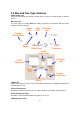
3. Plug an Ethernet cable into the Camera Connect an Ethernet cable to the LAN socket located on the Network Camera’s bottom and attach it to the network. 4. Connect the external power supply to Camera 5. Done 3. Camera administration When you installed your networked device over your network environment, to start Network Camera web configuration, you must have the web browsers installed on computer for web management. - Microsoft internet Explorer 6.
Note 1: If no IP address is assigned within 30 seconds, the networked device will automatically assign 192.168.0.100. User may now open your web browser, and key in http://192.168.0.100 in the address bar of you web browser to logon Network Camera’s web configuration page. Note 2: Power Line Frequency - If you found the video image is flash, you may need to choose 50 or 60 Hz frequency (depends on country).