LightningÔ 37xxxE Vector Network Analyzer Operation Manual 490 JARVIS DRIVE · MORGAN HILL, CA 95037-2809 P/N: 10410-00300 REVISION: A PRINTED: AUGUST 2010 COPYRIGHT 2010 ANRITSU CO.
WARRANTY The ANRITSU product(s) listed on the title page is (are) warranted against defects in materials and workmanship for three years from the date of shipment. ANRITSU’s obligation covers repairing or replacing products which prove to be defective during the warranty period. Buyers shall prepay transportation charges for equipment returned to ANRITSU for warranty repairs. Obligation is limited to the original purchaser. ANRITSU is not liable for consequential damages.
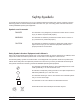
Safety Symbols To prevent the risk of personal injury or loss related to equipment malfunction, Anritsu Company uses the following symbols to indicate safety-related information. For your own safety, please read the information carefully BEFORE operating the equipment. Symbols used in manuals DANGER This indicates a very dangerous procedure that could result in serious injury or death if not performed properly.
For Safety WARNING Always refer to the operation manual when working near locations at which the alert mark, shown on the left, is attached. If the operation, etc., is performed without heeding the advice in the operation manual, there is a risk of personal injury. In addition, the equipment performance may be reduced. Moreover, this alert mark is sometimes used with other marks and descriptions indicating other dangers.
Narrative Table Of Contents Chapter 1—General Information This chapter provides a general description of the Anritsu Model 37xxxE Vector Network Analyzer System and its major units: network analyzer, test set, and frequency source. It also provides descriptions for the precision component kits, and equipment options. Additionally, it contains the listing of recommended test equipment.
Narrative Table of Contents (Continued) Chapter 7—Measurement Calibration This chapter provides a discussion and tutorial on measurement calibration. It contains step-by-step calibration procedures for the Standard (OSL), Offset-Short, TRM, and LRL/LRM methods. It also has a procedure for calibrating using a sliding termination. Chapter 8—Measurements This chapter discusses measurements with the 37xxxE VNA.
Table of Contents Chapter 1 General Information 1-1 SCOPE OF MANUAL . . . . . . . . . . . . . . . . . . . . . . . . . . . . . . . . . 1-3 1-2 INTRODUCTION . . . . . . . . . . . . . . . . . . . . . . . . . . . . . . . . . . . 1-3 1-3 IDENTIFICATION NUMBER. . . . . . . . . . . . . . . . . . . . . . . . . . . . . 1-3 1-4 ONLINE MANUALS. . . . . . . . . . . . . . . . . . . . . . . . . . . . . . . . . . 1-3 1-5 SYSTEM DESCRIPTION . . . . . . . . . . . . . . . . . . . . . . . . . . . . . . . 1-3 372xxE .
Table of Contents (Continued) 2-9 STORAGE OR SHIPMENT . . . . . . . . . . . . . . . . . . . . . . . . . . . . . 2-10 Preparation for Storage . . . . . . . . . . . . . . . . . . . . . . . . . . . . . . 2-10 Preparation for Shipment . . . . . . . . . . . . . . . . . . . . . . . . . . . . . 2-10 Chapter 3 Network Analyzers, A Primer 3-1 INTRODUCTION . . . . . . . . . . . . . . . . . . . . . . . . . . . . . . . . . . . 3-3 3-2 GENERAL DESCRIPTION . . . . . . . . . . . . . . . . . . . . . . . . . . . . . .
Table of Contents (Continued) 4-13 COMMAND LINE . . . . . . . . . . . . . . . . . . . . . . . . . . . . . . . . . . 4-41 Create Directory . . . . . . . . . . . . . . . . . . . . . . . . . . . . . . . . . . 4-42 List Directory . . . . . . . . . . . . . . . . . . . . . . . . . . . . . . . . . . . 4-42 Change Directory . . . . . . . . . . . . . . . . . . . . . . . . . . . . . . . . . 4-42 Delete Files. . . . . . . . . . . . . . . . . . . . . . . . . . . . . . . . . . . . . 4-42 Remove Directory . . . . . . .
Table of Contents (Continued) 6-7 HARD COPY AND STORAGE OUTPUT . . . . . . . . . . . . . . . . . . . . . . 6-15 Tabular Printout . . . . . . . . . . . . . . . . . . . . . . . . . . . . . . . . . . 6-15 Screen-Image Printout . . . . . . . . . . . . . . . . . . . . . . . . . . . . . . 6-15 Plotter Output . . . . . . . . . . . . . . . . . . . . . . . . . . . . . . . . . . . 6-15 Storage Output. . . . . . . . . . . . . . . . . . . . . . . . . . . . . . . . . . .
Table of Contents (Continued) 8-8 GAIN COMPRESSION. . . . . . . . . . . . . . . . . . . . . . . . . . . . . . . . 8-39 Power and VNAs . . . . . . . . . . . . . . . . . . . . . . . . . . . . . . . . . . 8-39 Swept Power Gain Compression . . . . . . . . . . . . . . . . . . . . . . . . . 8-41 Swept Frequency Gain Compression . . . . . . . . . . . . . . . . . . . . . . . 8-41 8-9 RECEIVER MODE . . . . . . . . . . . . . . . . . . . . . . . . . . . . . . . . . . 8-58 Source Lock Mode . . . . . . . . . . . . .
Table of Contents (Continued) 10-5 PHYSICAL SETUP . . . . . . . . . . . . . . . . . . . . . . . . . . . . . . . . . . 10-6 10-6 CHARACTERIZATION FILES . . . . . . . . . . . . . . . . . . . . . . . . . . . 10-7 10-7 USING AUTOCAL . . . . . . . . . . . . . . . . . . . . . . . . . . . . . . . . . . 10-9 10-8 PIN DEPTH SPECIFICATIONS . . . . . . . . . . . . . . . . . . . . . . . . . . 10-13 10-9 AUTOCAL MENUS FLOW DIAGRAM . . . . . . . . . . . . . . . . . . . . . .
Chapter 1 General Information Table of Contents 1-1 SCOPE OF MANUAL . . . . . . . . . . . . . . . . . . . . . . . . . . . . . . . . . 1-3 1-2 INTRODUCTION . . . . . . . . . . . . . . . . . . . . . . . . . . . . . . . . . . . 1-3 1-3 IDENTIFICATION NUMBER. . . . . . . . . . . . . . . . . . . . . . . . . . . . . 1-3 1-4 ONLINE MANUALS. . . . . . . . . . . . . . . . . . . . . . . . . . . . . . . . . . 1-3 1-5 SYSTEM DESCRIPTION . . . . . . . . . . . . . . . . . . . . . . . . . . . . . . . 1-3 372xxE .
Figure 1-1.
GENERAL INFORMATION SCOPE OF MANUAL Chapter 1 General Information 1-1 SCOPE OF MANUAL This manual provides general information, installation, and operating information for the Model 37xxxE Vector Network Analyzer (VNA) system. (Throughout this manual, the terms VNA, 37xxxE VNA, and 37xxxE will be used interchangeably to refer to the system.
OPTIONS GENERAL INFORMATION 372xxE 373xxE 1-6 OPTIONS The 372xxE is a fully functioning VNA for making passive-device measurements. The series offers three models that cover a range from 40 MHz to 65 GHz. The models are shown below: Model Frequency Range 37247E 40.0 MHz to 20.0 GHz 37269E 40.0 MHz to 40.0 GHz 37297E 40.0 MHz to 65.0 GHz The 373xxE is a fully functioning VNA for making passive- and active-device measurements.
GENERAL INFORMATION 1-7 PRECISION COMPONENT KITS Calibration Kits PRECISION COMPONENT KITS Two types of precision-component kits are available: calibration and verification. Calibration kits contain components used to identify and separate error sources inherent in microwave test setups. The Model 365X Calibration Kits contain all of the precision components and tools required to calibrate the VNA for 12-term error-corrected measurements of test devices with the connector type specified.
PERFORMANCE SPECIFICATIONS 1-8 1-9 1-6 GENERAL INFORMATION PERFORMANCE SPECIFICATIONS System performance specifications are provided in Appendix C. PREVENTIVE MAINTENANCE The 37xxxE VNA system does not require any preventive maintenance.
Chapter 2 Installation Table of Contents 2-1 INTRODUCTION . . . . . . . . . . . . . . . . . . . . . . . . . . . . . . . . . . . 2-3 2-2 INITIAL INSPECTION . . . . . . . . . . . . . . . . . . . . . . . . . . . . . . . . 2-3 2-3 PREPARATION FOR USE . . . . . . . . . . . . . . . . . . . . . . . . . . . . . . 2-3 Option 4, External SCSI Drive Setup . . . . . . . . . . . . . . . . . . . . . . . 2-4 2-4 GPIB SETUP . . . . . . . . . . . . . . . . . . . . . . . . . . . . . . . . . . . . .
Chapter 2 Installation 2-1 INTRODUCTION This chapter provides information for the initial inspection and preparation for use of the 37xxxE Vector Network Analyzer. Information for interfacing the 37xxxE to the IEEE-488 General Purpose Interface Bus and reshipment and storage information is also included. 2-2 INITIAL INSPECTION Inspect the shipping container for damage.
PREPARATION FOR USE Option 4, Additional SD Card for Secure Environments 2-4 INSTALLATION The 37xxxE is available with a second Secure Digital memory card (SD Card) for use in secure environments. This allows the VNA to be shipped with the System Software and Factory Cal Data on both the standard and additional SD Cards.
INSTALLATION 2-4 GPIB SETUP GPIB SETUP All functions of the 37xxxE (except power on/off and initialization of the SD Card) can be controlled remotely by an external computer/controller via the IEEE-488.2 GPIB. The information in this section pertains to interface connections and cable requirements for the rear panel GPIB connector. Refer to the Model 37xxxE Programming Manual, Anritsu Part Number 10410-00301, for information about remote operation of the 37xxxE using the GPIB.
SYSTEM GPIB INTERCONNECTION INSTALLATION 2-5 SYSTEM GPIB INTERCONNECTION GPIB Interface to an External Plotter GPIB Addresses 2-6 ETHERNET SETUP AND INTERCONNECTION There are two rear panel GPIB IEEE-488 connectors. The IEEE 488.2 connector used to interface the 37xxxE to an external computer/ controller via a standard GPIB cable. The Dedicated GPIB connector is used to interface to plotters and a second source for multiple source operation via a standard GPIB cable.
INSTALLATION ETHERNET SETUP AND INTERCONNECTION One known inconvenience is the actual assigned IP values do not refresh automatically on the screen. A quick way to do get them refreshed is to manually re-access the Network Utilities Menu, which will then display them correctly. The 37xxxE can be remotely controlled via a network server and an Ethernet connection via the standard RJ45 connector on the rear panel. The 37xxxE software supports the TCP/IP network protocol.
EXTERNAL MONITOR CONNECTOR 2-7 2-8 INSTALLATION EXTERNAL MONITOR CONNECTOR The rear panel External Monitor connector allows the internal display information of the 37xxxE to be connected to an external VGA monitor (either color or monochrome). The pinout of this 15-pin Type D connector is shown in Figure B-5, located in Appendix B. RACK MOUNT To install the Option 1 Rack Mount rails, refer to the below-listed procedure. Step 1. Disconnect the line cord and any other attachments from the instrument.
INSTALLATION RACK MOUNT Step 5. Remove the two side carrying handle screws (if so equipped) located under the plastic handle ends. Step 6. Remove the left and right side covers. These side covers are not reused in this application. Step 7. Install the two Rack Mount Handles using the green-headed screws removed earlier. Refer to Figure 2-2, on the following page, for the remainder of the assembly procedure. Step 8.
STORAGE OR SHIPMENT INSTALLATION Step 10. Secure the new right cover (3) from this retrofit kit to the right side chassis of the instrument by installing the center screw (6) through the center of the right side cover and the previously removed center screw at the rear of the right side cover. Step 11. Secure the slide assembly (4) to the right cover by installing the four mounting screws (5) to the right chassis. This completes the installation of the slide assembly.
Chapter 3 Network Analyzers, A Primer Table of Contents 3-1 INTRODUCTION . . . . . . . . . . . . . . . . . . . . . . . . . . . . . . . . . . . 3-3 3-2 GENERAL DESCRIPTION . . . . . . . . . . . . . . . . . . . . . . . . . . . . . . 3-3 Source Module. . . . . . . . . . . . . . . . . . . . . . . . . . . . . . . . . . . . 3-4 Test Set Module . . . . . . . . . . . . . . . . . . . . . . . . . . . . . . . . . . . 3-4 Analyzer Module . . . . . . . . . . . . . . . . . . . . . . . . . . . . . . . . . .
Chapter 3 Network Analyzers, A Primer 3-1 INTRODUCTION This section provides front panel operating and measurement application information and data.
GENERAL DESCRIPTION NETWORK ANALYZERS, A PRIMER INCIDENT TEST DEVICE TERMINATION REFLECTED Return Loss (dB) Reflection Coefficients (S11, S22) Reflection Coefficients vs Distance (Fourier Transform) Impedance (R + j X) SWR Figure 3-2. Reflection Measurements The 37xxxE is a self-contained, fully integrated measurement system that includes an optional time domain capability.
NETWORK ANALYZERS, A PRIMER 3-3 NETWORK ANALYZERS NETWORK ANALYZERS We will begin this discussion with a subject familiar to most Anritsu customers: scalar network analysis. After showing comparisons, we will proceed to the fundamentals of network analyzer terminology and techniques. This discussion serves as an introduction to topics presented in greater detail later in this section.
NETWORK ANALYZERS A NETWORK ANALYZER IS A TUNED RECEIVER INTERMEDIATE FREQUENCY (IF) MICROWAVE SIGNAL TUNABLE LOCAL OSCILLATOR • GREATER DYNAMIC RANGE • LESS SENSIVITY TO INTERFERING SIGNALS Figure 3-4. NETWORK ANALYZERS, A PRIMER Vector Network Analyzer Basics The network analyzer is a tuned receiver (Figure 3-4, left). The microwave signal is down converted into the passband of the IF. To measure the phase of this signal, we must have a reference to compare it with.
NETWORK ANALYZERS, A PRIMER REFERENCE SIGNAL TEST SIGNAL PHASE DETECTOR MICROWAVE SOURCE SPLITTER LONGER BY ONE WAVELENGTH LENGTH (360 degrees) Figure 3-8. TEST SIGNAL PHASE DETECTOR MICROWAVE SOURCE SPLITTER SAME PATH LENGTH -BUTWAVELENGTH IS NOW SHORTER 1.1 WAVELENGTHS = 396 degrees MEASURED PHASE Assume that we are making a measurement at 1 GHz and that the difference in path-length between the two signals is exactly 1 wavelength.
NETWORK ANALYZERS NETWORK ANALYZERS, A PRIMER MEASURED PHASE There are two ways of accomplishing this. The most obvious way is to insert a length of line into the reference signal path to make both paths of equal length (Figure 3-11, below). With perfect transmission lines and a perfect splitter, we would then measure a constant phase as we change the frequency. The problem using this approach is that we must change the line length with each measurement setup. +180 REFERENCE SIGNAL +90 0 1.1 1.2 1.
NETWORK ANALYZERS, A PRIMER NETWORK ANALYZERS Network Analyzer Measurements PORT 1 FORWARD REFLECTION Figure 3-14. PORT 2 DUT REVERSE REFLECTION Forward and Reverse Measurements S21 FORWARD TRANSMISSION PORT 1 S11 FORWARD REFLECTION PORT 2 DUT S22 REVERSE REFLECTION Now let us consider measuring the DUT. Consider a two port device; that is, a device with a connector on each end.
NETWORK ANALYZERS There are several ways in which all the information can be displayed on one trace. One method is a polar display (Figure 3-17). The radial parameter (distance from the center) is magnitude. The rotation around the circle is phase. We sometimes use polar displays to view transmission measurements, especially on cascaded devices (devices in series). The transmission result is the addition of the phase and log magnitude (dB) information of each device’s polar display.
NETWORK ANALYZERS, A PRIMER NETWORK ANALYZERS Another important parameter we can measure when phase information is available is group delay. In linear devices, the phase change through the DUT is linear-with-frequency. Thus, doubling the frequency also doubles the phase change. An important measurement, especially for communications system users, is the rate of change-of-phase-vs.-frequency (group delay). If the rate of phase-change-vs.-frequency is not constant, the DUT is nonlinear.
Chapter 4 Front Panel Operation Table of Contents 4-1 INTRODUCTION . . . . . . . . . . . . . . . . . . . . . . . . . . . . . . . . . . . 4-3 4-2 KEY-GROUPS . . . . . . . . . . . . . . . . . . . . . . . . . . . . . . . . . . . . . 4-3 4-3 CALIBRATION KEY-GROUP . . . . . . . . . . . . . . . . . . . . . . . . . . . . 4-10 4-4 SAVE/RECALL MENU KEY . . . . . . . . . . . . . . . . . . . . . . . . . . . . . 4-20 4-5 MEASUREMENT KEY-GROUP 4-6 CHANNELS KEY-GROUP . . . . . . . . . . . . . . . . . . . . . .
24 Data Entry Menu 7 8 9 4 5 6 1 2 3 MHz X1 ns cm 3 GHz 10 us m 23 Enter -3 kHz 10 ps mm 0 .
Chapter 4 Front Panel Operation 4-1 INTRODUCTION This chapter describes the front panel keys, controls, and menus. The chapter is organized into an overall description of the front panel key-groups and detailed descriptions of individual keys within the key-groups. 4-2 KEY-GROUPS The following pages provide descriptions of the front panel key-groups illustrated in Figure 4-1 on the previous page. Index 1. LCD display: Displays any or all of the four measurement channels, plus menus. Index 2.
KEY-GROUPS FRONT PANEL OPERATION Index 4. System State Keys: (Refer to section 4-10, page 4-33, for details and menu flow diagrams.) Default Program: Resets the front panel to the factory-preset state and displays Menu SU1 or SU3 (Appendix A). Pressing this key in conjunction with the “0” or “1” key resets certain internal memories and front panel key states (refer to sections 4-5 and 4-10).
FRONT PANEL OPERATION KEY-GROUPS Index 12. Save/Recall Menu Key: Displays the first of several menus that let you save the current calibration or front panel setup or recall a previously saved calibration or setup. Refer to section 4-4, page 4-20, for menu flow diagram. Index 13. Markers/Limits Keys: (Refer to section 4-11, page 4-36, for details and menu flow diagrams.) Marker Menu: Displays the first in a series of menus that let you set and manipulate marker frequencies, times, and distances.
KEY-GROUPS FRONT PANEL OPERATION Index 17. Display Keys: (Refer to section 4-7, page 4-25, for details and menu flow diagrams.) Graph Type: Displays the two menus that let you choose the graph type for the active channel. Set Scale: Displays the appropriate scaling menu, based on the graph type for the active channel. Auto Scale: Automatically scales the active channel for optimum viewing. S Params: Displays Menu SP (Appendix A), which lets you choose between S11, S12, S21, or S22.
FRONT PANEL OPERATION Index 19. KEY-GROUPS Enhancement Keys: (Refer to section 4-8, page 4-29 for details and menu flow diagrams.) Option Menu: Displays a series of menus showing the choice of optional features. Video IF BW: Displays a menu that lets you chose between 10 kHz, 1 kHz, 100 Hz, or 10 Hz intermediate frequency (IF) bandwidth filters. Avg/Smooth Menu: Displays a menu that lets you enter values for Averaging and Smoothing. Trace Smooth: Turns the trace smoothing function on and off.
KEY-GROUPS FRONT PANEL OPERATION Index 21. Channels Keys: (Refer to section 4-6, page 4-24, for details and menu flow diagrams.) Channel Menu: Displays a menu that lets you select the format for the number of channels displayed. Ch 1: Makes Channel 1 the active channel. The active channel is the one acted on by the keys in the Display section. Only one channel can be active at any one time. Ch 2: Makes Channel 2 the active channel. Ch 3: Makes Channel 3 the active channel.
FRONT PANEL OPERATION Index 23. KEY-GROUPS Data Entry Keys: Rotary Knob: Used to alter measurement values for the active parameter (Start Frequency, Stop Frequency, Offset, etc.). Keypad: Provides for entering values for the active parameter. The active parameter is the one to which the menu cursor is pointing.
CALIBRATION KEY-GROUP 4-3 FRONT PANEL OPERATION The Calibration keys (Begin Cal and Apply Cal, below) are described below. The calibration menus are diagramed according to the method of calibration performed: Standard, Offset-Short, TRM or LRL/LRM. The menu sequencing is complex and looping and can be said to have two parts: setup and calibration. The setup flow for the four calibration methods is diagramed in Figures 4-3 through 4-6.
FRONT PANEL OPERATION CALIBRATION KEY-GROUP Standard Calibration Setup Flow—Description 1. Pressing the Begin Cal key calls Menu C11. 2. With one exception, the flow is from left to right in the direction of the arrow head. The exception occurs in Menu C1, for the TIME DOMAIN choice. Here the flow direction reverses to Menu C2C then returns to a left-to-right flow on to Menu C3 or C3D. 3.
CALIBRATION KEY-GROUP FRONT PANEL OPERATION M E N U M E N U M E N U B e g in C a l C 1 1 B E G IN C A L IB R A T IO N K E E P E X IS T IN G C A L D A T A R E P E A T P R E V IO U S C A L N E X T C A L S T E P T o M e n u S U 1 /S U 3 * T o C a l S e q ** C A L M E T H O D S T A N D A R D S O L T (S T A N D A R D ) S S S T (T R IP L E O F F S E T S H O R T ) T R A N S M IS S IO N L IN E T Y P E : X X X X X X X X S E L E C T 1 P A T H 2 P O R T C A L IB R A T IO N T Y P E F O R W A R D P A T H (S 1
FRONT PANEL OPERATION CALIBRATION KEY-GROUP SSLT and SSST (Offset-Short) Calibration Setup Flow—Description 1. Pressing the Begin Cal key calls Menu C13. 2. With one exception, the flow is from left to right in the direction of the arrow head. The exception occurs in Menu C1, for the TIME DOMAIN choice. Here the flow direction reverses to Menu C2C then returns to a left-to-right flow on to Menu C3A, C3C, or C3B. 3.
FRONT PANEL OPERATION CALIBRATION KEY-GROUP M E N U M E N U C 1 1 A M E N U T o M e n u S U 1 /S U 3 * C 1 1 B E G IN C A L IB R A T IO N B e g in C a l T o C a l S e q ** C A L M E T H O D S T A N D A R D T R A N S M IS S IO N L IN E T Y P E : X X X X X X X X L R L /L R M P R E S S < E N T E R > T O S E L E C T X X X D A T A P O IN T S X X X .X X X X X X X X X G H z S T E P S IZ E A X X X X X P P T S P T S P T S P T S P T S T S A S P A N X X X .
FRONT PANEL OPERATION CALIBRATION KEY-GROUP LRL/LRM Calibration Setup Flow—Description 1. Pressing the Begin Cal key calls Menu C15. 2. With one exception, the flow is from left to right in the direction of the arrow head. The exception occurs in Menu C1, for the TIME DOMAIN choice. Here the flow direction reverses to Menu C2C then returns to a left-to-right flow on to Menu C3E, C3G, or C3F. 3.
CALIBRATION KEY-GROUP FRONT PANEL OPERATION M E N U M E N U C 1 1 M E N U K E E P E X IS T IN G C A L D A T A T o M e n u S U 1 /S U 3 * R E P E A T P R E V IO U S C A L T o C a l S e q ** A U T O C A L C A L M E T H O D S T A N D A R D T R A N S M IS S IO N L IN E T Y P E : X X X X X X X X C H A N G E C A L M E T H O D A N D L IN E T Y P E C 1 1 A C A L F R E Q B E G IN C A L IB R A T IO N B e g in C a l M E N U C H A N G E C A L M E T H O D A N D L IN E T Y P E C 2 R A N G E S T A R T X X
FRONT PANEL OPERATION CALIBRATION KEY-GROUP TRM Calibration Setup Flow—Description 1. Pressing the Begin Cal key calls Menu C17. 2. With one exception, the flow is from left to right in the direction of the arrow head. The exception occurs in Menu C1, for the TIME DOMAIN choice. Here the flow direction reverses to Menu C2C then returns to a left-to-right flow on to Menu C3H, C3J, or C3I. 3.
CALIBRATION KEY-GROUP FRONT PANEL OPERATION M E N U M E N U C 1 1 M E N U C A L F R E Q B E G IN C A L IB R A T IO N B e g in C a l K E E P E X IS T IN G C A L D A T A T o M e n u S U 1 /S U 3 * R E P E A T P R E V IO U S C A L T o C a l S e q ** A U T O C A L C A L M E T H O D S T A N D A R D T R A N S M IS S IO N L IN E T Y P E : X X X X X X X X M E N U C 1 1 A C H A N G E C A L M E T H O D A N D L IN E T Y P E C 2 C A L F R E Q S T A R T X X X .
FRONT PANEL OPERATION CALIBRATION KEY-GROUP From Standard, Offset-Short, and LRL/LRM Calibration Flowcharts MENU C7, C8, C9 Series CALIBRATION SEQUENCE CONNECT CALIBRATION DEVICE(S) CAL_MEAS_DEV MEASURING PORT 1: XXXXXXXXXXXX PORT 2: XXXXXXXXXXXX PRESS TO MEASURE DEVICE(S) MENU CAL_NEXT_DEV P R E S S FOR NE XT C AL S TE P OR P R ES S TO R E-ME A SU R E YES CAL DONE NO PRESS <1> FOR PORT 1 DEVICE GO TO NEXT CAL STEP PRESS <2> FOR PORT 2 DEVICE MENU CAL_C
SAVE/RECALL MENU KEY 4-4 SAVE/RECALL MENU KEY FRONT PANEL OPERATION Pressing this key displays the first of a menu set (below) that lets you save or recall control panel setups and calibration data. Full menu descriptions can be found in the alphabetically ordered Appendix A under the menu’s call letters (SR1, SR2, SR3, etc).
FRONT PANEL OPERATION 4-5 MEASUREMENT KEY-GROUP MEASUREMENT KEY-GROUP The individual keys within the Measurement key-group are described below. Flowcharts of the Setup Key and Data Points key menus are shown in Figure 4-8. As described for the calibration menus, the flow is left-to-right and the double arrowhead lines indicate that the flow returns to the calling menu once a selection has been made.
MEASUREMENT KEY-GROUP Figure 4-8.
FRONT PANEL OPERATION MEASUREMENT KEY-GROUP Figure 4-8.
CHANNELS KEY-GROUP 4-6 CHANNELS KEY-GROUP FRONT PANEL OPERATION The individual keys within the Channels key-group are described below: Ch 1-4 Keys: These keys (below) define the active channel. One (and only one) must always be active as indicated by the associated LED. Pressing a button makes the indicated channel active. If channel indicated by the key is already active, pressing the key has no effect.
FRONT PANEL OPERATION 4-7 DISPLAY KEY-GROUP DISPLAY KEY-GROUP The individual keys within the Display key-group are described below. Menu flow diagrams are shown in Figure 4-10. Full menu description(s) for menu SP and all others mentioned below can be found in the Appendix A alphabetical listing under the menu’s call letters (SP, GT1, RD1, etc.). Graph Type Key: Pressing this key calls menu GT1 or GT2.
DISPLAY KEY-GROUP FRONT PANEL OPERATION On menu RD1, selecting AUTO automatically adjusts the reference delay to unwind the phase for the active channel.
FRONT PANEL OPERATION DISPLAY KEY-GROUP Figure 4-10.
DISPLAY KEY-GROUP FRONT PANEL OPERATION D is p la y S e t S c a le G ra p h T y p e A u to S c a le R e f P la n e S P a ra m s T ra c e M e m o ry M E N U N O 1 T R A C E M E M O R Y F U N C T IO N S V IE W V IE W M E N U D S 1 1 , U S E R b 2 / 1 M E N U S 2 2 , R E V b 2 / a 2 R E F L M E N U M E N U R A T IO M E N U P R E S S < 1 > T O R E D E F IN E S E L E C T E D P A R A M E T E R (R a ) a 2 (R b ) A U T O A IR (1 .
FRONT PANEL OPERATION 4-8 ENHANCEMENT KEY-GROUP ENHANCEMENT KEY-GROUP The individual keys within the Enhancement key-group are described below. Full menu description(s) for menu OPTNS and all others mentioned below can be found in the Appendix A alphabetical listing under the menu’s call letters (OPTNS, EM, CAL_BW, etc). Option Menu Key: This key brings up the OPTNS menu. Depending on choices selected, this menu causes other menus to appear.
ENHANCEMENT KEY-GROUP Figure 4-12.
FRONT PANEL OPERATION 4-9 HARD COPY KEY-GROUP HARD COPY KEY-GROUP The individual keys within the Hard Copy key-group are described below. Full descriptions for menus can be found in the alphabetical listing (Appendix A) under the menu’s call letters (PM1, PM2, PM3, etc.) Menu Key: Pressing this key brings up menu PM1. This menu allows you to define what will happen every time you press the Start Print key. A menu flow diagram is shown in Figure 4-13.
HARD COPY KEY-GROUP FRONT PANEL OPERATION USB DRIVE SD CARD USB DRIVE SD CARD USB DRIVE Figure 4-13.
FRONT PANEL OPERATION 4-10 SYSTEM STATE KEY-GROUP SYSTEM STATE KEY-GROUP The individual keys within the System State key-group are described below. The menu flow for the Utility Menu key is shown in Figure 4-14 on page 4-35. Full descriptions for menus can be found in the alphabetical listing (Appendix 1) under the menu’s call letters (U1, U2, U3, etc.) Default Program Key: Pressing this key brings up the default menu.
SYSTEM STATE KEY-GROUP FRONT PANEL OPERATION Table 4-2.
FRONT PANEL OPERATION SYSTEM STATE KEY-GROUP USB SD CARD SD CARD USB SD CARD USB SD CARD USB DRIVE SD CARD USB DRIVE USB Figure 4-14.
MARKERS/LIMITS KEY-GROUP 4-11 MARKERS/LIMITS KEY-GROUP FRONT PANEL OPERATION The individual keys within the Markers/Limits key-group are described below. The menu flow for the Marker Menu key is shown in Figure 4-15 on the following page. Full descriptions for these menus can be found in the alphabetical listing (Appendix A) under the menu’s call letters (M1, M2, M3, etc.) Marker Menu Key: Pressing the Marker Menu key calls Menu M1.
FRONT PANEL OPERATION MARKERS/LIMITS KEY-GROUP Figure 4-15.
MARKERS/LIMITS KEY-GROUP FRONT PANEL OPERATION Markers/Limits Markers/Limits Markers/Limits Markers/Limits Limits Limits Limits Limits MENU L2 MENU L1 MENU L3 SINGLE LIMITS SINGLE LIMITS - LOG MAG - DISPLAY ON(OFF) LIMITS A READOUT LIMIT B TEST LIMITS - PHASE - PRESS TO SELECT OR TURN ON/OFF UPPER LIMIT ON/OFF XXX.XXX ˚ - LOG MAG - UPPER LIMIT ON(OFF) XXX.XXX mV LOWER LIMIT ON(OFF) XXX.XXX mV LOWER LIMIT ON(OFF) XXX.
FRONT PANEL OPERATION Markers/Limits MARKERS/LIMITS KEY-GROUP Limits MENU L9 SINGLE LIMITS UPPER LIMIT ON(OFF) XXX.XXX pU LOWER LIMIT ON(OFF) XXX.XXX dB LOWER LIMIT ON(OFF) XXX.XXX pU UPPER LIMIT ON/OFF XXX.
STORAGE INTERFACE 4-12 STORAGE INTERFACE Disk Files FRONT PANEL OPERATION The 37xxxE has two internal storage devices: a 8 GB SD Card and a USB 2.0 storage interface. The format, directory structure, and files are compatible with MS-DOS, Version 5.0 and above. The following file types may be found on the 37xxxE SD Card: q Program Files: Binary files used to load the operating program. They are provided on the SD Card and a backup copy is provided on a USB drive. Application programs cannot read them.
FRONT PANEL OPERATION Disk File Output Device COMMAND LINE You can select the output drive destination for the disk file as either the SD Card (C:) or the USB drive (A:). The format of the file is also selected. The default condition is a text file to the SD Card. You may then proceed with normal measurements. The Start Print key may then be used at the instant you intend to capture the data.
COMMAND LINE FRONT PANEL OPERATION q DELETE FILES (DEL) q REMOVE DIRECTORY (RD) q COPY FILES (COPY) These options are NOT case sensitive. Create Directory List Directory This command is performed by: MD c:\pat-h\dir_name or MD a:\path\dir_name. The c: is used to refer to the SD Card, and a: is for the USB drive. This command is performed by “DIR” command. This may be used as DIR c:\path or without any path specified. The syntax is: DIR c:\path or DIR a:\path.
FRONT PANEL OPERATION Remove Directory COMMAND LINE This command is used to delete a particular directory. The command is only valid when the entire directory is empty: q RD c:\path\directory q RD a:\path\directory Copy Files This command is performed by the command line COPY source: destination: COPY c:\path\name a:\path\name Any combination of the drive is allowed, except for the same directory, and the same name.
COMMAND LINE FRONT PANEL OPERATION Vector Network Analyzer Clear/Ret Loc _____ Esc Start Print ________ Hold _____________ Print Screen, F12 Pause Default Program Avg/Smooth Menu Channel Menu Utility Menu Options Menu Ctrl Trace Smooth A v e ra ge V ide o I F B W Alt Marker Menu Readout Marker Limits Shift Ch 1 Ch 2 Ch 3 Ch 4 F3 F4 Command Line Recall S a ve S Params Graph Type Set Scale Auto Scale Copyright (c) 1994-2010 by Anritsu Company F1 Alt Default Program Avg/Smooth Menu
Chapter 5 Error and Status Table of Contents 5-1 INTRODUCTION . . . . . . . . . . . . . . . . . . . . . . . . . . . . . . . . . . . 5-3 5-2 ERROR MESSAGES. . . . . . . . . . . . . . . . . . . . . . . . . . . . . . . . . .
Chapter 5 Error and Status Messages 5-1 INTRODUCTION This chapter lists, describes, and provides corrective action for the error messages that point to problems that the operator can correct. Any error messages that appear on the display but do not appear in this chapter will require action by a qualified service representative. 5-2 ERROR MESSAGES Error messages are provided in Tables 5-1 and 5-2. Table 5-1.
ERROR MESSAGES Table 5-1. ERROR AND STATUS MESSAGES General Error Messages (2 of 3) Error Message Description Corrective Action NO STORED MEMORY DATA No data is stored in the USB drive or SD Card memory. None. OPTION NOT INSTALLED Selected an option that is not installed. None. OUT OF CAL RANGE Entered values out of the selected calibration range. Change calibration range or re-enter values that are within the current range.
ERROR AND STATUS MESSAGES Table 5-1. ERROR MESSAGES General Error Messages (3 of 3) Error Message Description Corrective Action STOP IS OVER RANGE Entered value exceeds the instrument’s stop frequency. Re-enter stop frequency. SYSTEM BUS ADDRESSES MUST BE UNIQUE GPIB address is being used by another bus instrument. Select a different, unique GPIB address. SYSTEM UNCALIBRATED 37xxxE is uncalibrated for the selected measurement values. Perform a measurement calibration.
ERROR MESSAGES Table 5-3. ERROR AND STATUS MESSAGES Ethernet-Related-Error Messages (1 of 1) Error Message Description Corrective Action INVALID IP REQUESTED An Invalid IP is requested. Enter a valid IPv4 compatible address. IP IS RESERVED IP Entered is a reserved IP Examples of reserved IPs: 127.x.x.x x.0.0.0 x.0.0.1 255.255.255.255 Addresses ending in 0 or 255 CHANGES TO INT.
Chapter 6 Data Displays Table of Contents 6-1 INTRODUCTION . . . . . . . . . . . . . . . . . . . . . . . . . . . . . . . . . . . 6-3 6-2 DISPLAY MODES AND TYPES . . . . . . . . . . . . . . . . . . . . . . . . . . . 6-3 Single Channel Display: Ch 1, 2, 3, 4. . . . . . . . . . . . . . . . . . . . . . . . 6-3 Dual Channel Display: Ch 1 and 3 or Ch 2 and 4 . . . . . . . . . . . . . . . . . 6-4 Four Channel Display: Ch 1, 2, 3, 4 . . . . . . . . . . . . . . . . . . . . . . . . 6-5 Dual Trace Overlay . . . . .
Chapter 6 Data Displays 6-1 6-2 INTRODUCTION This chapter provides discussion and examples of the various types of data displays. DISPLAY MODES AND TYPES The 37xxxE displays measurement data using a “Channel Concept.” This means that each channel can display both a different S-Parameter and a different graph type. As you select each channel, the graph type, scaling, reference delay, S-Parameter, etc., associated with that channel appears on the screen.
DISPLAY MODES AND TYPES DATA DISPLAYS S11 FORWARD REFLECTION LOG MAG. REF= 0.000 dB 0.040000000 GHz PHASE Figure 6-2. Dual Channel Display: Ch 1 and 3 or Ch 2 and 4 10.000 dB/DIV REF= 20.000000000 0.00 | 90.00 | /DIV Single Channel Display, Magnitude and Phase If you have chosen a dual display of magnitude and phase, the affected area of the LCD screen is subdivided into two smaller portions (Figure 6-3). You select this display type by choosing “Dual Display” in Menu CM (Appendix A).
DATA DISPLAYS Four Channel Display: Ch 1, 2, 3, 4 DISPLAY MODES AND TYPES From four-to-eight graph types are displayed. In each quadrant, the graph type can be any of the possible choices listed in the GT menu (Appendix A). If you have chosen to display magnitude and phase on a channel, the quadrant displaying that channel is further subdivided as described above. You select this display type by choosing “All Four Channels” in Menu CM. An example of a four-channel display appears in Figure 6-4, below.
DISPLAY MODES AND TYPES Dual Trace Overlay DATA DISPLAYS For rectilinear graph types, two traces can be displayed, one overlaid (superimposed) on the other (Figure 6-5). By menu selection, the two traces can be Channel 1 overlaid on Channel 3 or Channel 2 overlaid on Channel 4. Each trace is in a different color. Channels 1 and 2 are displayed in red, while Channels 3 and 4 are displayed in yellow. CH1:S11 FWD REFL CH3:S21 FWD TRANS LOG MAG. LOG MAG. REF= 0.000 dB REF= 10.000 dB/DIV 2.
DATA DISPLAYS Graph Data Types DISPLAY MODES AND TYPES The data types (real, imaginary, magnitude, phase) used in the displayed graph-types reflect the possible ways in which S-Parameter data can be represented in polar, Smith, or rectilinear graphs.
DISPLAY MODES AND TYPES DATA DISPLAYS S11 FWD REFL REF= 1.000 U 200.000 mU/DIV 90 LINEAR POLAR 135 45 180 0 0 -135 -45 -90 Figure 6-6. Linear Polar Graticule S21 FORWARD TRANSMISSION LOG MAG. REF= -38.569 dB REF= 483.588 mU 2.036000000 S21 FORWARD TRANSMISSION LINEAR MAG. 2.036000000 Figure 6-7. 6-8 GHz GHz 20.000 dB/DIV 10.020000000 200.000 mU/DIV 10.
DATA DISPLAYS DISPLAY MODES AND TYPES S21 FWD TRANS REF= 0.000 dB 1.000 dB/DIV 90 LOG POLAR 135 45 180 0 -135 -45 -90 Figure 6-8. Log Polar Graticule S11 FORWARD REFLECTION 1 IMPEDANCE 2 .5 .2 5 0 .2 .5 1 2 5 -5 -.2 -.5 -2 -1 2.036000000 - Figure 6-9. 37xxxE OM 10.
DISPLAY MODES AND TYPES DATA DISPLAYS S11 FORWARD REFLECTION 1 IMPEDANCE .5 2 .2 -.17 0 .2 .5 1 2 5 -5.8 -.2 -2 -.5 -1 2.036000000 - Figure 6-10. 10.020000000 GHz 3 dB Compressed Smith Chart S11 FORWARD REFLECTION .20 IMPEDANCE .15 .10 .05 0 .82 .85 .90 .95 1.0 1.05 1.10 1.15 1.20 -.05 -.10 -.15 20 Figure 6-11.
DATA DISPLAYS 6-3 FREQUENCY MARKERS FREQUENCY MARKERS The example below shows how the 37xxxE annotates markers for the different graph-types. Each marker is identified with its own number. When a marker reaches the top of its graticule, it will flip over and its number will appear below the symbol. When markers approach the same frequency, they will overlap. Their number will appear as close to the marker as possible without overlapping. S11 S12 -20.000 dB 1 Z LOGM+P 10.000 dB/DIV 2 .5 .
STATUS DISPLAY DATA DISPLAYS Each channel has two limit lines (four for dual displays), each of which may take on any value. Limit lines are either horizontal lines in rectilinear displays or concentric circles around the origin in Smith and polar displays. Each channel can produce segmented limits. They allow different upper and lower limit values to be set at up to ten segments across the measurement range.
DATA DISPLAYS Measurement Status Sweep Indicator Marker 6-6 DATA DISPLAY CONTROL DATA DISPLAY CONTROL The 37xxxE displays measurement-status messages (in red when appropriate) in the upper-right corner of the graticule (channel) to which they apply. A blue sweep-indicator marker appears at the bottom of each displayed graph-type. It indicates the progress of the current sweep.
DATA DISPLAY CONTROL S-parameter Selection Data Display Update DATA DISPLAYS If you select a new S-parameter using Menu SP (Appendix A), it appears on the then-active channel in the same graph-type in which it was last displayed. The following table shows the displayable S-parameters based on the correction type you have in place. If you attempt to display other S-parameters, an error message appears. In cases when there is no last-displayed S-parameter stored, the display will default as shown.
DATA DISPLAYS HARD COPY AND STORAGE OUTPUT resolution, that frequency and the marker will continue to display. It will display even if its frequency is not consistent with the data points in the lower-resolution sweep.
HARD COPY AND STORAGE OUTPUT Figure 6-14.
Chapter 7 Measurement Calibration Table of Contents 7-1 INTRODUCTION . . . . . . . . . . . . . . . . . . . . . . . . . . . . . . . . . . . 7-3 7-2 DISCUSSION . . . . . . . . . . . . . . . . . . . . . . . . . . . . . . . . . . . . . 7-3 Establishing the Test Ports . . . . . . . . . . . . . . . . . . . . . . . . . . . . . 7-3 Understanding the Calibration System . . . . . . . . . . . . . . . . . . . . . . 7-5 Calibrating for a Measurement . . . . . . . . . . . . . . . . . . . . . . . . . .
Chapter 7 Measurement Calibration 7-1 INTRODUCTION This section provides discussion and examples for performing a measurement calibration. It also provides a detailed procedure for calibrating with a sliding termination. 7-2 DISCUSSION Measurements always include a degree of uncertainty due to imperfections in the measurement system. The measured value is always a combination of the actual value plus the systematic measurement errors.
DISCUSSION MEASUREMENT CALIBRATION The use of cables and/or adapters does not effect the final measurement result, if they were in place for the calibration process. The vector error corrections established during the calibration process eliminates cable and/or adapter effects as long as the ports used are stable and exhibit good repeatability. Figure 7-2 shows such a configuration. ADAPTERS PORT 1 PORT 2 Figure 7-2.
MEASUREMENT CALIBRATION DISCUSSION This approach offers two advantages: q It minimizes wear on the more expensive test set and cable connectors q It provides a simple solution to measuring non-insertable devices (e.g., a filter with K female input and output connectors) by merely swapping PEAs after calibration. See Figure 7-4 NOTE In this and other discussions, we will talk about “insertable” and “non-insertable” devices. Insertable devices have an insertable connector pair (i.e.
DISCUSSION MEASUREMENT CALIBRATION duced through improved technique and training, and frequency errors can be virtually eliminated by the fully synthesized internal source. ERRORS REDUCED BY CALIBRATION · Directivity · Source Match · Load Match · Frequency Sensitivity (Tracking) · Isolation We know that adapters and cables degrade the basic directivity of the system, but these errors are compensated by vector error correction.
MEASUREMENT CALIBRATION DISCUSSION Reflection Only: Corrects for the three error terms associated with an S11 measurement (EDF, ESF, and ERF), an S22 measurement (EDR, ESR, and ERR), or both.
DISCUSSION MEASUREMENT CALIBRATION PORT 1 E XF 1 PORT 1 PORT 2 PORT 2 S21M S11 E SF DUT ETF DUT EDF S22 S2 1 RF IN S21 ERR ELR ELF S22 S11 ESR EDR S22 S12 ETR 1 S12M ERF RF S12 EXR S11M Forward Direction Terms Reverse Direction Terms 12 - TERM E XF PORT 1 PORT 1 PORT 2 S21M RF IN S21 PORT 2 S21 RF IN S21 ETF ETF DUT DUT 1 Path - 2 Port Terms Frequency Response - Transmission Only Terms EDF S11 E SF ERF S11M PORT 1 PORT 1 PORT 2 RF IN PORT 2 RF IN DUT
MEASUREMENT CALIBRATION Calibrating for a Measurement CALIBRATING FOR A REFLECTION MEASUREMENT USES THREE STANDARDS: · Short · Open · Termination IDEAL TERMINATIONS · Reflectionless · Perfect Connector · Infinite-Length, Dimensionally Exact, Reflectionless Transmission Line PRACTICAL Zo TERMINATIONS · Broadband Load · Sliding Termination 37xxxE OM DISCUSSION Let us assume that we want to correct for three errors in the reflection measurement: source match, directivity, and tracking.
DISCUSSION BROADBAND LOAD · Easy to Use · Inexpensive · Adequate for Most Applications SLIDING LOAD · Connector · Long Transmission Line · Movable Microwave Load MEASUREMENT CALIBRATION Broadband loads are widely used. An example is the Anritsu 28 Series Termination. These terminations are easy to use as calibration tools, and they are adequate for most applications. Sliding Loads are the traditional vector network analyzer Z0 calibration reference.
MEASUREMENT CALIBRATION Evaluating the Calibration DISCUSSION The 37xxxE provides an accurate representation of complex data. However, it can only provide accuracy to the extent of the supplied calibration data. For this reason, it is necessary to periodically verify the calibration data and the 37xxxE system performance. Calibration verification reveals problems such as a poor contact with one of the calibration components, improper torquing, or a test port out of specification.
DISCUSSION MEASUREMENT CALIBRATION The verification of the kit components is straight forward. The components are first measured with the 37xxxE, then they are compared with the data recorded on the USB drive. If the measured data compares favorably with the recorded data (taking tolerances into consideration), then the system is known to be operating properly and providing accurate data. There is one caution that you need to observe when using Verification Kits.
MEASUREMENT CALIBRATION 7-3 SLIDING TERMINATION SLIDING TERMINATION Sliding terminations (loads) are the traditional Z0 calibration-reference devices for vector network analyzer calibration. When correctly used and perfectly aligned, they can be more accurate than precision fixed loads. However, sliding terminations have a 2 GHz (4 GHz for V-Connector sliding loads) low-frequency limit and must be used with a fixed load for full frequency-range coverage.
SLIDING TERMINATION 7-14 MEASUREMENT CALIBRATION Step 2. Push the outer locking ring towards the gauge to expose the center pin. Step 3. Take the 01-210 Ref Flat from the kit. Step 4. While holding the gauge as shown, press the Ref Flat firmly against the end of the exposed center pin.
MEASUREMENT CALIBRATION Step 5. SLIDING TERMINATION While pressing the Ref Flat against the center pin, check that the pointer aligns with the “0” mark. If it does not, loosen the bezel lockscrew and rotate the bezel to align the pointer with the “0” mark. Tighten the bezel lock screw. NOTE Gently rock the Ref Flat against the center pin to ensure that it is fully depressed and you have accurately set the gauge for zero. 37xxxE OM Step 6.
SLIDING TERMINATION 7-16 MEASUREMENT CALIBRATION Step 9. Remove the flush short by holding its body and unscrewing its connector. Step 10. Install the gauge onto the end of the sliding termination. Step 11. If the COARSE SET adjustment—which has been set at the factory—has not moved, the inner dial on the gauge will read “0.” If it doesn’t, perform the Coarse Set Adjustment in Step 15. Step 12. Place the sliding termination, with the gauge attached, on the bench top.
MEASUREMENT CALIBRATION SLIDING TERMINATION Step 13. Loosen the FINE LOCK ring and turn the FINE ADJ ring to position the gauge pointer 2-3 small divisions on the “–” side of zero. Step 14. Turn the FINE LOCK ring clockwise to both tighten the adjustment and place the pointer exactly to “0.” The Sliding Termination is now ready to use. NOTES Ensure that the inner dial reads “0.” The following step is not normally necessary.
SLIDING TERMINATION 7-18 MEASUREMENT CALIBRATION Step 17. Remove the 01-223 Female Adapter (“F ADAPTER FOR PIN GAUGE”) from the kit. Step 18. Install the female adapter over the center pin and screw it into the locking ring, and tighten the outer ring until it is snug against the housing. Step 19. Inspect the end of the adapter, you should see no more than two exposed threads. If so, repeat Steps 7 through 10. Step 20.
MEASUREMENT CALIBRATION 7-4 SOLT CALIBRATION Calibration Procedure SOLT CALIBRATION The SOLT calibration for the 37xxxE Vector Network Analyzer system uses a Short, Open, Load, and a Thru line connection to categorize the inherent errors in the measurement system. These errors include those caused by connectors as well as internal system errors such as RF leakage, IF leakage, and component interaction. For maximum accuracy, install the capacitive coefficients (for the open device) using Menu U3.
SOLT CALIBRATION MEASUREMENT CALIBRATION Step 3. MENU C11A CHANGE CAL METHOD AND LINE TYPE When menu C11A (left) appears, move the cursor to the following: a. SOLT (STANDARD), then press the Enter key. This selects Standard (SOLT) as the calibration method. NEXT CAL STEP CAL METHOD b. COAXIAL, then press the Enter key. This selects coaxial transmission line media. SOLT (STANDARD) SSLT (DOUBLE OFFSET SHORT WITH LOAD) c. NEXT CAL STEP, then press the Enter key.
MEASUREMENT CALIBRATION Step 7. MENU C1 SELECT CALIBRATION DATA POINTS SOLT CALIBRATION Next, menu C1 appears. It lets you select the number of frequency points at which calibration data is to be taken. The choices are: a. NORMAL: Data is taken at up to 1601 equally spaced frequencies across the calibration frequency range. Use this selection for this example. NORMAL (1601 POINTS MAXIMUM) b. C.W.: Data is taken at one point.
SOLT CALIBRATION MEASUREMENT CALIBRATION Step 9. When menu C3 (left) appears, if you want to change any of the parameters shown in blue letters, place the cursor on that parameter and press the Enter key. For this example, we will change them all, starting with the top one. Move the cursor to PORT 1 CONN and press the Enter key. Step 10. In menu C4 (below), which appears next, move the cursor to K CONN (M) and then press the Enter key.
MEASUREMENT CALIBRATION SOLT CALIBRATION Step 11. With menu C3 (left) displayed, move the cursor to PORT 2 CONN and press the Enter key. Following the procedure in Step 10, select K CONN (M) for the Port 2 connector. Step 12. When menu C3 returns: MENU C3 CONFIRM CALIBRATION PARAMETERS PORT 1 CONN K CONN (M) PORT 2 CONN K CONN (M) REFLECTION PAIRING MIXED LOAD TYPE SLIDING THROUGH PARAMETERS REFERENCE IMPEDANCE TEST SIGNALS START CAL PRESS TO SELECT OR CHANGE a.
SOLT CALIBRATION MEASUREMENT CALIBRATION Step 13. MENU C3 CONFIRM CALIBRATION PARAMETERS PORT 1 CONN TYPE N (M) PORT 2 CONN TYPE N (F) When menu C3 returns: a. Observe that REFLECTION PARING now reflects MIXED. b. Move cursor to LOAD TYPE and press the Enter key. This brings up menu C6 (below).
MEASUREMENT CALIBRATION Step 14. SOLT CALIBRATION When menu C3 again returns: MENU C20 a. Observe that LOAD TYPE now shows BROADBAND. ENTER THROUGH LINE PARAMETERS b. Move cursor to THROUGH PARAMETERS and press the Enter key. OFFSET LENGTH 0.0000 mm THROUGHLINE IMPEDANCE 50.000 W Step 15. Menu C20 (left) appears next. It lets you define the length of the offset and the impedance of the throughline. For this example, enter 0 mm for length and 50 ohms for impedance. Step 16.
SOLT CALIBRATION MEASUREMENT CALIBRATION Step 18. When menu C3 returns, select TEST SIGNALS to bring up menu SU2 (left). Step 19. Menu SU2 lets you define the power level of the signals at the two test ports. Power delivered to the DUT by the test set must be such that the measured signals are well above the noise floor but below the 0.1 dB compression level of the Test Set samplers. (Noise floor and maximum signal into Port 2 levels are specified in Appendix C.) MENU SU2 TEST SIGNALS POWER CONTROL 0.
MEASUREMENT CALIBRATION Step 20. MENU C3 CONFIRM CALIBRATION PARAMETERS PORT 1 CONN TYPE N (M) PORT 2 CONN SMA (M) SOLT CALIBRATION When menu C3 reappears, select START CAL and press the Enter key to begin the calibration procedure. Continue the calibration sequence by following the prompts as they appear. Connect the appropriate Isolation Devices, Broadband Loads, Opens, Shorts, and Throughlines, when requested in the calibration sequence.
OFFSET-SHORT CALIBRATION (SSLT) 7-5 MEASUREMENT CALIBRATION OFFSET-SHORT CALIBRATION (SSLT) The Offset-Short calibration, now also referred to as the Double Offset-Short Calibration, is the standard technique for waveguide; however, this method can be used for the coaxial and microstrip line types as well. It uses two shorts, two loads, and a thru line to categorize the inherent errors in the waveguide measurement system.
MEASUREMENT CALIBRATION Step 3. MENU C11A CHANGE CAL METHOD AND LINE TYPE OFFSET-SHORT CALIBRATION (SSLT) When menu C11A (left) appears, move cursor to the following: a. SSLT (DOUBLE OFFSET SHORT), then press the Enter key. This selects Offset Short as the calibration method. NEXT CAL STEP CAL METHOD SOLT (STANDARD) b. WAVEGUIDE, then press the Enter key. This brings menu C5 (bottom left) to the screen. SSLT (DOUBLE OFFSET SHORT WITH LOAD) c. NEXT CAL STEP, then press the Enter key.
OFFSET-SHORT CALIBRATION (SSLT) Step 7. Menu C1 (left), which appears next, lets you select the number of frequency points at which calibration data is to be taken. Of these choices, which were described in paragraph 7-4, choose NORMAL (1601 POINTS MAXIMUM) for this example. Step 8. The next menu, C2 (below), lets you set your start and stop frequencies. For this example, move cursor to START, press 40 on keypad, and press the MHz terminator key.
MEASUREMENT CALIBRATION OFFSET-SHORT CALIBRATION (SSLT) Step 10. When menu C15 (left) appears, move cursor to one of the two available choices and press the Enter key. These choices are described below. MENU C15 SELECT WAVEGUIDE KIT TO USE a. USE INSTALLED WAVEGUIDE KIT: Selecting this choice uses the values shown in blue for IDENTIFIER, CUTOFF FREQ, SHORT 1, and SHORT 2. Select this choice, for this example. –INSTALLED KIT— IDENTIFIER XXXX CUTOFF FREQ: XXX.XXXXXXXXX GHz b.
TRIPLE OFFSET-SHORT CALIBRATION (SSST) CALIBRATION 7-6 TRIPLE OFFSET-SHORT CALIBRATION (SSST) Calibration Procedure MEASUREMENT The Triple Offset-Short calibration method can be used in coax, waveguide, and microstrip line types, and is most accurate when used over narrower frequency ranges. As the name implies, this method uses three offset-shorts to categorize the inherent errors in the measurement system.
MEASUREMENT CALIBRATION (SSST) Step 3. MENU C11A TRIPLE OFFSET-SHORT CALIBRATION When menu C11A (left) appears, move cursor to the following: a. SSST (TRIPLE OFFSET SHORT), then press the Enter key. This selects Triple Offset-Short as the calibration method. CHANGE CAL METHOD AND LINE TYPE NEXT CAL STEP SOLT (STANDARD) b. COAXIAL, then press the Enter key. This brings menu C5 (left) to the screen. SSLT (DOUBLE OFFSET SHORT WITH LOAD) c. NEXT CAL STEP, then press the Enter key.
TRIPLE OFFSET-SHORT CALIBRATION (SSST) CALIBRATION Step 7. Menu C1 appears next (left) and lets you select the number of frequency points for which calibration data is to be taken. Select NORMAL (1601 POINTS MAXIMUM) (refer to section 7-4 for a description). Step 8. The next menu, C2 (below), lets you set your start and stop frequencies. For this example, move the cursor to START, press 65 on the keypad, then press the GHz terminator key.
MEASUREMENT CALIBRATION (SSST) TRIPLE OFFSET-SHORT CALIBRATION Step 10. When menu C3B (left) appears, if you want to change any of the parameters shown in blue letters, place the cursor on that parameter and press the Enter key. Step 11. When menu C3 (lower left) returns: MENU C3B CONFIRM CALIBRATION PARAMETERS WAVEGUIDE PARAMETERS INSTALLED a. Observe that PORT 1 CONN and PORT 2 CONN now reflects W1 CONN (M). REFLECTION PAIRING MIXED b. Move the cursor to REFLECTION PARING and press the Enter key.
LRL/LRM CALIBRATION 7-7 LRL/LRM CALIBRATION MEASUREMENT CALIBRATION The LRL/LRM (line-reflect-line/line-reflect-match) calibration* feature provides an enhanced capability for error compensation when making measurements in coaxial, microstrip and waveguide transmission media. Instead of using the standard Open, Short, and Load, the LRL/LRM calibration method uses two lines and a reflection or match.
MEASUREMENT CALIBRATION LRL/LRM Calibration (Microstrip) LRL/LRM CALIBRATION Microstrip is a dispersive media. The 37xxxE applies dispersion compensation during calibration for microstrip measurements.
LRL/LRM CALIBRATION MEASUREMENT CALIBRATION Step 3. Select CHANGE CAL METHOD AND LINE TYPE, in menu C11 (left). (This assumes LRL and MICROSTRIP are not presently shown in blue as being selected.) Step 4. When menu C11A (bottom left) appears, highlight the following selections. MENU C11 BEGIN CALIBRATION KEEP EXISTING CAL DATA REPEAT PREVIOUS CAL a. LRL/LRM and press the Enter key. AUTOCAL CAL METHOD XXXXXXXX b. MICROSTRIP and press the Enter key. TRANSMISSION LINE TYPE: XXXXXXXX c.
MEASUREMENT CALIBRATION Step 7. When menu C3G appears, if you want to change microstrip parameters to be different from those shown in blue, place the cursor on MICROSTRIP PARAMETERS and press the Enter key. Step 8. When menu C16 (left) appears, move the cursor to the Anritsu 3680 UTF calibration kit you wish to use or to USER DEFINED; then press the Enter key.
LRL/LRM CALIBRATION MENU C3G CONFIRM CALIBRATION PARAMETERS LRL/LRM PARAMETERS CHANGE MICROSTRIP PARAMETERS XXXXXXXXX START CAL PRESS TO SELECT MENU C18 CHANGE LRL/LRM PARAMETERS NEXT CAL STEP MEASUREMENT CALIBRATION Step 9. Select LRL/LRM PARAMETERS, when menu C3G returns. Step 10. When menu C18 appears, you have two choices to make: whether your calibration is to be two-line or three-line, and where you want to have your reference plane. a.
MEASUREMENT CALIBRATION LRL/LRM CALIBRATION Step 11. When menu C18A (left) appears, make the following selections (for 2-line): MENU C18A CHANGE LRL/LRM PARAMETERS NEXT CAL STEP CHARACTERIZE CAL DEVICES DEVICE 1 LINE 1 (REF) X.XXXX mm DEVICE 2 LINE /MATCH X.XXXX mm PRESS TO SELECT OR SWITCH a. Move the cursor to DEVICE 1 LINE 1 (REF) and key in the value. b. Move the cursor to DEVICE 2 LINE/MATCH. Here you have another decision to make: whether your calibration is to be LRL or LRM.
LRL/LRM CALIBRATION MEASUREMENT CALIBRATION Step 12. When menu C18B (left) appears, make the following selections (for 3-line): MENU C18B CHANGE LRL/LRM PARAMETERS NEXT CAL STEP CHARACTERIZE CAL DEVICES DEVICE 1 LINE 1 (REF) XX.XXXX DEVICE 2 LINE/MATCH XX.XXXX/LOWBAND DEVICE 3 LINE/MATCH XX.XXXX/HIGHBAND FREQ AFTER WHICH THE USE OF DEVICE 2 AND DEVICE 3 IS EXCHANGED BREAKPOINT XXX.XXXXXXXXXGHZ PRESS TO SELECT OR SWITCH a.
MEASUREMENT CALIBRATION Step 13. LRL/LRM CALIBRATION The next menu, C19, gives you choices for your reflective device. MENU C19 a. Move the cursor to REFLECTION OFFSET LENGTH and key in a value (typically 0.0000 mm). CHANGE LRL/LRM PARAMETERS NEXT CAL STEP REFLECTION OFFSET LENGTH +XXX.XXXX mm b. Move the cursor to GREATER THAN Z0 or LESS THAN Z0, depending on whether your reflective device is an Open or a Short. Press the Enter key to select.
LRL/LRM CALIBRATION LRL/LRM Calibration (Coaxial) MEASUREMENT CALIBRATION An LRL cal kit is necessary to perform the coaxial calibration. Calibration kits for GPC-7 are available from Maury Microwave and Agilent. Two line lengths are used as the impedance standard. The calibration frequency range is limited by the difference in the lengths of the two lines. Their length must be different by approximately 90 degrees at the mid-band frequency.
MEASUREMENT CALIBRATION LRL/LRM CALIBRATION Consideration must also be given to selecting the breakpoint frequency. Divide the frequency range to satisfy the 9:1 rule for any given pair of lines. The range is thus divided by the frequency breakpoint into the intervals [f1, f2] and [f2, f3]. Based on these intervals, next determine the appropriate length differences; the longer difference is associated with the lower interval [f1, f2].
TRM CALIBRATION LRL/LRM Calibration (Waveguide) MEASUREMENT CALIBRATION The waveguide procedure is very similar to the coaxial and microstrip procedures already described. Step 1. MENU C3F CONFIRM CALIBRATION PARAMETERS The only difference is with menu C3F (left). For a waveguide calibration, move the cursor to WAVEGUIDE CUTOFF FREQ and press Enter. This action calls menu C15B, which lets you enter the waveguide cutoff frequency. After doing so, you are returned to menu C3F.
MEASUREMENT CALIBRATION 7-9 MERGE CAL FILES APPLICATION MERGE CAL FILES APPLICATION The Merge Cal Files application allows the user to combine two or more calibrations that were performed on the VNA, but having differing frequency ranges. This is of particular importance when a wide band RF calibration cannot be performed because wide band calibration components, such as loads and shorts, are not available. Such a case exists when using Anritsu’s 37x97E wideband VNAs.
Chapter 8 Measurements Table of Contents 8-1 INTRODUCTION . . . . . . . . . . . . . . . . . . . . . . . . . . . . . . . . . . . 8-3 8-2 TRANSMISSION AND REFLECTION . . . . . . . . . . . . . . . . . . . . . . . . 8-3 8-3 LOW LEVEL AND GAIN . . . . . . . . . . . . . . . . . . . . . . . . . . . . . . 8-12 8-4 GROUP DELAY . . . . . . . . . . . . . . . . . . . . . . . . . . . . . . . . . . . 8-20 8-5 ACTIVE DEVICE . . . . . . . . . . . . . . . . . . . . . . . . . . . . . . . . . .
Chapter 8 Measurements 8-1 8-2 INTRODUCTION This section discusses typical measurements that can be made with the Model 37xxxE Vector Network Analyzer. TRANSMISSION AND REFLECTION This discussion provides information on general measurement considerations and transmission and reflection measurements using the 37xxxE. Setup and Calibration To get started, apply power to the system. After turning on the power, allow the system to warm up for at least 60 minutes before operation.
TRANSMISSION AND REFLECTION MEASUREMENTS Install the calibration kit devices to the test ports as instructed by the U3 menu. Both the capacitance coefficients for the Open and the offset lengths for the Open and Short can be modified or defined. Selecting the Begin Cal key starts the calibration process. The Calibration menus step you through the calibration process, as follows: Select the type of calibration desired. Select the frequency range of calibration.
MEASUREMENTS TRANSMISSION AND REFLECTION Up to six markers are available. Using the Marker Menu, you can set the frequency of each one, you can set each one in the delta marker mode, and you can set each marker’s level to maximum or minimum. In some cases—such as in a production environment—limit lines are desirable. Options within the menu called up using the Limits key, provide for one or two flat, sloped, or single-point-segmented limit lines for each channel.
TRANSMISSION AND REFLECTION MEASUREMENTS To label the output, select Setup Output Headers in the Output Menu or press the Device ID key. On the output to the printer, plotter, or storage drive. a menu then appears that lets you specify the device name/serial number, the date, the operator’s name, and user comments (Figure 8-2).
MEASUREMENTS TRANSMISSION AND REFLECTION Finally, you can enhance the measurement data by reducing the IF bandwidth and using averaging and/or smoothing.
TRANSMISSION AND REFLECTION MEASUREMENTS IM A G IN A R Y M A G N IT U D E P H A S E R E A L R E F L E C T IO N C O E F F IC IE N T = P H A S E = Figure 8-4. R E F L E C T IO N (M A G N IT U D E ) IN C ID E N T (M A G N IT U D E ) IN C ID E N T (P H A S E ) - R E F L E C T E D (P H A S E ) Magnitude/Phase Vector The measurement reference for the incident energy is the point at which the device connects to the measurement system. We call this point the reference plane.
MEASUREMENTS TRANSMISSION AND REFLECTION Let us assume both that our system is already calibrated and that we have equalized the system for the test port in use. We would then 1. Connect the Short: A Short always appears as a dot at the left-most edge of the Smith chart’s horizontal axis. 2. Connect a Termination: Now you will see another dot located at the center (1+j0) of the chart (this assumes a 50-ohm load). 3. Connect the Open: An Open appears as an arc on the chart’s right edge.
TRANSMISSION AND REFLECTION MEASUREMENTS Now let’s perform a reflection measurement on a 20 dB attenuator over the 1 to 18 GHz range. We need to determine the setup, calibration, and measurement requirements. A known good starting point is to reset with Default Program parameters. Since our measurement lies between 1 and 18 GHz, set the Start and Stop frequencies using the Sweep Setup menu that appears on the display following system reset.
MEASUREMENTS TRANSMISSION AND REFLECTION Now let us perform a transmission measurement on the same 20 dB attenuator over the same frequency range. We will follow the same steps as before, but this time we will use additional features. Once again, reset the system using the Default Program key. In this calibration we will select the N-Discrete Frequencies menu option and step all frequencies in increments of 50 MHz.
LOW LEVEL AND GAIN 8-3 LOW LEVEL AND GAIN MEASUREMENTS This discussion provides methods and techniques for making gain and low-signal-level measurements. It is divided into 37xxxE system considerations and test device considerations. 37xxxE System Considerations The 37xxxE system is limited in its ability to test low-signal levels by its dynamic range and signal-to-noise-power ratio.
MEASUREMENTS LOW LEVEL AND GAIN The detected signal is the vector sum of the desired signals, the noise signals, and the leakage signals. These signals introduce an error or uncertainty (Figure 8-8). D E T E C T E D O U T P U T S IG N A L U N C E R T A IN T Y RNAY M G A II N O IS E S IG N A L L E A K A G E O R F A L S E S IG N A L M E A S U R E D S IG N A L A C T U A L S IG N A L P H A S E E R R O R R E A L Figure 8-8.
LOW LEVEL AND GAIN MEASUREMENTS M A X U N C E R T A IN T Y F O R M A G N IT U D E A S A F U N C T IO N O F S /N R A T IO 1 0 0 .0 1 0 .0 M A X IM U M U N C E R T A IN T Y (d B m ) 1 .0 .1 .0 1 .0 0 1 .0 0 0 1 0 Figure 8-9. 1 0 5 0 6 0 2 0 3 0 4 0 S IG N A L /N O IS E R A T IO (d B ) The Effect of S/N Ratio On Magnitude Measurements (Noise Only) M A X U N C E R T A IN T Y F O R P H A S E A S A F U N C T IO N O F S /N R A T IO 1 0 0 .0 1 0 .0 M A X IM U M U N C E R T A IN T Y (D E G R E E S ) 1 .0 .
MEASUREMENTS LOW LEVEL AND GAIN The most difficult types of measurements are those that exercise the full dynamic range of the 37xxxE, such as filters (Figure 8-11. Filter measurements are examples of where one must observe both low-insertion loss (in the passband) and high attenuation (in the stop band). B A N D P A S S F IL T E R S 2 1 d B < 1 d B P A S S B A N D 0 d B > 5 0 d B S T O P B A N D F R E Q U E N C Y Figure 8-11.
LOW LEVEL AND GAIN MEASUREMENTS Averaging is another way to improve accuracy. The improvement is proportional to the square root of the number of averages. Two types of averaging are supported: Sweep-by-sweep and point-by-point. Point-by-point averaging works by collecting multiple measurements while at each frequency point and then averaging them together.
MEASUREMENTS LOW LEVEL AND GAIN Test Device (DUT) Considerations In order to test a device, the required input RF level and the expected device output RF level must be determined. The RF level at Port 1 must be set for the device input RF power level required. Attenuation can be added in steps of 10 dB up to 70 dB using the built-in source attenuator. Amplification can be added by removing the front panel loop and adding an external amplifier.
LOW LEVEL AND GAIN MEASUREMENTS The 37xxxE uses enhancements in the calibration to ensure a wide dynamic range. It automatically selects 1 kHz IF bandwidth and varies the number of averages with the calibration device. Terminations require the most averages. If desired, the Video IF bandwidth and number of averages can be specified for the calibration measurements. Using 100 averages (Avg = 100) appears to be sufficient for most measurements.
MEASUREMENTS LOW LEVEL AND GAIN Wide Dynamic Range Device - Filter Since you do both low-insertion-loss and high- attenuation measurements simultaneously, use the maximum RF signal level and no attenuation. Selecting the 1 kHz Video IF BW setting and 100 averages will likely suffice for this kind of measurement (Figure 8-13). B A N D P A S S F IL T E R S 2 1 d B < 1 d B P A S S B A N D 0 d B > 5 0 d B S T O P B A N D F R E Q U E N C Y Figure 8-13.
GROUP DELAY 8-4 GROUP DELAY MEASUREMENTS Group delay is the measure of transit time through a device at a particular frequency. Ideally, we want to measure a constant—or relatively constant—transit time over frequency. The top waveform shown in Figure 8-14 is measured at one frequency. The bottom waveform is identical to the first, simply delayed in time. M A G N IT U D E t Figure 8-14.
MEASUREMENTS GROUP DELAY When designing components it is important to measure group delay so that you can compensate for any distortion caused by the component. You may be able to tune the device so as to optimize the performance of group delay over the frequency range of interest. Outside of the specified frequency range, the group delay may or may not be linear. So how is group delay measured? Signals travel too fast to enable measuring the input and output times of each frequency component.
GROUP DELAY MEASUREMENTS Let us take a look at a group delay measurement made on the Anritsu 37347E Vector Network Analyzer. Group delay, as a measurement option, can be found in the Graph Type menu. After selecting the option, the VNA displays the data in a time-vs-frequency graph, or to be more exact, a group-delay-vs-frequency graph (Figure 8-17). S 2 1 F O R W A R D G R O U P D E L A Y 3 .0 0 0 0 Figure 8-17. T R A N S M IS S IO N R E F = 1 .0 0 0 n S G H z 6 0 0 .0 0 0 p S /D IV 9 .
MEASUREMENTS GROUP DELAY The aperture defaults to the smallest setting for the frequency range and number of data points selected. This value is displayed in the Set Scale key menu when measuring group delay (Figure 8-19). S 2 1 F O R W A R D T R A N S M IS S IO N G R O U P D E L A Y R E F = 1 .0 0 0 n S 3 .0 0 0 0 Figure 8-19. G H z 6 0 0 .0 0 0 p S /D IV 9 .
ACTIVE DEVICE 8-5 ACTIVE DEVICE MEASUREMENTS Active devices are key components in microwave systems. The measurements that are made on active devices are similar to those made on passive devices. Active devices come in many shapes and sizes. In most cases we are going to have to develop a fixture in which to mount the device. Active devices require bias voltages, and in many cases they are easily damaged. High gain amplifiers may saturate with input signals of –50 dBm.
MEASUREMENTS ACTIVE DEVICE Test fixtures are necessary for mounting the device so that it can be measured in our coaxial (or waveguide) measuring system (Figure 8-21). Figure 8-21. Active Device Test Fixture Now we have an interesting situation. While we can measure the performance at the connector—which is the calibration plane—what we really want to know is how our device performs (Figure 8-22). F E T G P C -7 G P C -7 S S Figure 8-22.
ACTIVE DEVICE MEASUREMENTS 5 0 O H M L IN E G P C -7 D U T N O Figure 8-23. L O S S , R E F L E C T IO N L E S S Simple Example of De-Embedding In some cases—depending on the fixture or the device being measured—this is satisfactory. But when it is not, we need to employ other techniques.
MEASUREMENTS ACTIVE DEVICE In the discussion on calibration we saw that the calibration components establish the reference plane and determine the quality of the measurement. If we have a good Open, Short and Z0 load to place at the end of a microstrip line, we can calibrate the system at the point of measurement. Figure 8-25 shows some of the special test-fixture calibration standards that are available. Figure 8-25.
ACTIVE DEVICE MEASUREMENTS CAUTION You should turn off or disconnect the bias supplies during the calibration, since you are using a Short as the calibration standard. It is also possible to use three known impedances. For instance, a varactor with three voltages applied (Figure 8-27). S P E C IA L C A L IB R A T IO N K IT S C 1 C 2 C IS V A R IE D B Y C H A N G IN G V O L T A G E C 3 N O T P E R F E C T E IT H E R Figure 8-27. Three Known Impedances The second approach is to model the fixture.
MEASUREMENTS 8-6 MULTIPLE SOURCE CONTROL MULTIPLE SOURCE CONTROL The Multiple Source Control mode permits independent control of the 37xxxE source, receiver, and an external Anritsu synthesizer (67xxB, 68xxxB, MG369xx), without the need of an external controller (Figure 8-28). 1. Remove a1 loop on the front panel (Opt. 15 only). 2. Set up equipment as shown. 3. Normalize the data trace with the standard mixer installed. 4.
MULTIPLE SOURCE CONTROL MENU U1 SELECT UTILITY FUNCTION OPTIONS GPIB ADDRESSES DISPLAY INSTRUMENT STATE PARAMS MEASUREMENTS Multiple Source Control Pre-operational Setup The two sources receive control information from the 37xxxE VNA. The GPIB address assigned to the external source must be identical to the address contained in the data directed to the source by the 37xxxE VNA. Assure source/VNA address compatibility as follows: Step 1. Install Sources 1 and 2 on the Dedicated GPIB bus. Step 2.
MEASUREMENTS MULTIPLE SOURCE CONTROL Multiple Source Control Operation MENU OPTNS OPTIONS Step 5. Press the Option Menu key. TRIGGERS REAR PANEL OUTPUT . - Channels Measurement Display Enhancement DIAGNOSTICS MULTIPLE SOURCE CONTROL RECEIVER MODE SOURCE CONFIG RF ON/OFF DURING RETRACE PRESS TO SELECT MENU OM1 MULTIPLE SOURCE CONTROL Option Menu Step 6. When menu OPTIONS (left) appears, move cursor to MULTIPLE SOURCE CONTROL and press the Enter key. Step 7.
MULTIPLE SOURCE CONTROL Step 8. MENU OM2 DEFINE BANDS BAND 1 DISPLAYED FREQ RANGE Band 1 must start at the beginning of the frequency range and end at either the user-specified stop frequency or the end of the frequency range. BAND STOP F XXX.XXXXXXXXX GHz BAND FUNCTIONS EDIT SYSTEM EQUATIONS Band 2 must begin at the next point after band 1 ends and end at either the user-specified stop frequency or the end of the frequency range.
MEASUREMENTS MULTIPLE SOURCE CONTROL Step 17. Move the cursor to PREVIOUS MENU and press the Enter key. This returns you to menu OM2 (left). Step 18. Move cursor to STORE BAND 1 and press the Enter key. This stores the band start frequency, the band stop frequency and the Source 1, Source 2 and Receiver equations. BAND START F XX.XXXXXX GHz Step 19. Note that the BAND number has incremented to 2. BAND STOP F XX.XXXXXX GHz Step 20.
ADAPTER REMOVAL 8-7 ADAPTER REMOVAL MEASUREMENTS Using adapters in VNA measurement applications can introduce complex errors that add to measurement uncertainty. The VNA Adapter Removal procedure provides for adapter compensation. This on-screen, menu-driven procedure allows the use of a through-line device or adapter with different connector types (non-insertables) on either end to be used for measurement calibration. The electrical effects are subsequently compensated for.
MEASUREMENTS ADAPTER REMOVAL Step 4. Figure 8-29. 37xxxE OM Follow the on-line procedure and connect the Adapter’s N male connector (X’) to the N female connector on the VNA’s Test Port 1.
ADAPTER REMOVAL MEASUREMENTS Step 5. Press the Begin Cal key (below). MENU SR1 SAVE/RECALL FRONT PANEL AND CAL DATA . SAVE - Channels Measurement Display Enhancement RECALL SET UP OUTPUT HEADERS PRESS TO SELECT FUNCTION Begin Cal Apply Cal Step 6. Follow the menu prompts and choose to perform a full 12-term calibration. Use the Adapter’s SMA male connector (Y') as Test Port 1 and the VNA’s Test Port 2 connector as Test Port Y. Step 7. Press the Save/Recall Menu key (below).
MEASUREMENTS MENU CAR1 ADAPTER REMOVAL Step 12. Press the Begin Cal key again. Step 13. Follow the menu prompts; again choose to perform a full 12-term calibration. Now use the Adapter’s Type N male connector (X’) as Test Port 2. Use the VNA’s Test Port 1 connector as Test Port X. Step 14. Save the calibration as described in Steps 7 and 8, above. Give this file a unique filename, such as X_XPRIME.CAL. (Store this file in the current directory.) Step 15.
ADAPTER REMOVAL MEASUREMENTS Step 19. Move the cursor to the appropriate READ CAL FILE OF THE Y TEST PORT. . . choice (top left) and press the Enter key. Step 20. Observe that the text READING . . . FROM DISK appears in the menu area. Step 21. When the file has finished reading, the procedure is complete and the program returns to the SWEEP SETUP menu (below).
MEASUREMENTS 8-8 GAIN COMPRESSION GAIN COMPRESSION There are a number of ways to measure Gain Compression. With a VNA two approaches are possible: Swept Frequency Gain Compression (SFGC) and Swept Power Gain Compression (SPGC). The 37xxxE offers a very straightforward approach to each of these measurements.
GAIN COMPRESSION MEASUREMENTS Gain Compression Power Configuration Amplifier Specifications: Frequency Range: 8 to 12 GHz Gain 25 dB nominal 1 dB Gain Compression (GC) 12 dBm minimum Gain Compression Formula: P = 12 – 25 – 15 = –28 dBm 37369E Setup Default Power: –7 dBm Power Control: –8 dB Port 1 Attenuator: 0 dB External Port 1 Attenuator: 10 dB The above setting result in Port 1 Power: –25 dBm Maximum Amplifier Output Figure 8-28.
MEASUREMENTS GAIN COMPRESSION Errors can result if the proper correction factor is not applied by the power meter, as shown below. Correction Factor (%) Error (dB) 1 0.043 3 0.128 5 0.212 10 0.414 It is desirable to set the power control at or near the minimum (this varies from −20 to−30 dB, depending upon model) when establishing P, as this provides the full ALC range for a power sweep. The vector error correction available in VNAs is dependent upon ratioed S-parameter measurements.
GAIN COMPRESSION Figure 8-30.
MEASUREMENTS GAIN COMPRESSION Swept Power Gain Compression Measurement The following procedures describes the Swept Power Gain Compression Measurement. Step 1. Press the Appl key. MENU APPL ADAPTER REMOVAL . SWEPT FREQUENCY GAIN COMPRESSION - Channels Measurement Display Enhancement SWEPT POWER GAIN COMPRESSION E/O MEASUREMENTS O/E MEASUREMENTS MERGE CAL FILES PRESS TO SELECT Appl NOTE A 12-Term S-parameter calibration is not necessary for gain compression calibration and measurement.
GAIN COMPRESSION MENU GC_DF2 SWEPT POWER FREQUENCIES INPUT A FREQ, PRESS TO INSERT SWEPT POWER FREQUENCY 12.000000000 GHz CLEAR FREQ NUMBER 1 CLEAR ALL FINISHED, RETURN TO POWER SWEEP SETUP PRESS TO SELECT MEASUREMENTS Move cursor to FINISHED, RETURN TO POWER SWEEP SETUP and press Enter. Move cursor to P START (previous page), set per power plan (Figure 8-28), and press Enter. Move cursor to P STOP (previous page), set per power plan, and press Enter.
MEASUREMENTS GAIN COMPRESSION Step 4. MENU GC3 SWEPT POWER GAIN COMPRESSION CALIBRATE FOR LINEARITY ([NO] CAL EXIST) Move the cursor to CALIBRATE FOR LINEARITY, press Enter, and follow the instructions that (1) appear adjacent to the follow-on menu and (2) are described below. If a calibration already exists, the menu choice will indicate CAL EXIST in blue letters.
GAIN COMPRESSION MEASUREMENTS Wait until one complete sweep has completed, then press Enter to store the calibration. MENU GC3 SWEPT POWER GAIN COMPRESSION LINEARITY ON [OFF] CORRECTION NOTE It is likely that the trace will be off screen at the bottom of the display. If so, press Autoscale to obtain a discernable trace. If this trace shows vertical instability, then do the following: CALIBRATE RECEIVER ([NO] CAL EXISTS) 1. Press Video IF BW and select REDUCED (100 Hz) from the menu.
MEASUREMENTS GAIN COMPRESSION Step 10. Observe that the SWEPT POWER SETUP menu and the dual-trace display resembles that shown below. Step 11. Press Readout Marker (below) for a display of gain compression at the marker frequency. MENU SU3A SWEPT POWER SETUP SWEPT POWER FREQUENCY 9.000000000 GHz P START –25.00 dBm P STOP –5.00 dBm STEP SIZE 1.
GAIN COMPRESSION MEASUREMENTS Step 13. MENU SU3A Press Setup Menu (below) to return to SWEPT POWER SETUP menu. SWEPT POWER SETUP SWEPT POWER FREQUENCY 9.000000000 GHz . - Channels Measurement Display Enhancement P START –25.00 dBm P STOP –5.00 dBm STEP SIZE 1.00 dB Setup Menu POWER SWEEP ON HOLD BUTTON FUNCTION Step 14. Move cursor to SWEPT POWER FREQUENCY (top left), select the next frequency from the SET FREQUENCY list, and press Enter. RETURN TO SWEPT FREQUENCY MODE Step 15.
MEASUREMENTS GAIN COMPRESSION Step 18. Repeat Steps 13 through 16 until all desired frequencies have been observed. Step 19. If desired, a multiple frequency gain compression display can be obtained by selecting MULTIPLE FREQUENCY GAIN COMPRESSION (left) and pressing Enter. Step 20. Move cursor to TEST AUT (top left) and press Enter. Step 21. Observe that the Multiple Frequency Gain Compression display resembles that shown below. Step 22.
GAIN COMPRESSION MEASUREMENTS Step 24. Move cursor to RETURN TO SWEPT FREQUENCY MODE and press Enter to exit the gain compression mode. NOTE When exiting the Swept Frequency Power Gain Compression mode, the DUT should be turned off, unless the user has selected the proper attenuator settings for standard swept frequency (S-parameter) operation.
MEASUREMENTS GAIN COMPRESSION Swept Frequency Gain Compression Measurement The following procedure describes the Swept Frequency Gain Compression Measurement. ADAPTER REMOVAL Preliminary: Refer to Figure 8-28 and set the Power Control and Port 1 Attenuator for the values shown in the power plan for the example, or in the power plan constructed for measurement of a test device.
GAIN COMPRESSION MEASUREMENTS NOTE This step is not required for a successful gain compression measurement; however, calibrating the power from Port 1 (which is what this step does) provides increased accuracy. Prepare the power meter as described in the following instructions: a. Preset, zero, and calibrate the power meter. b. Set power meter offset, if required. c. Connect the power meter to the dedicated GPIB interface and the power sensor to the test port. d. Select .
MEASUREMENTS GAIN COMPRESSION Step 4. MENU GC1 SWEPT FREQUENCY GAIN COMPRESSION Move cursor to CALIBRATE RECEIVER and follow the instructions, as follows: NOMINAL OFFSET -10.00 dB Connect a through line between Test Port 1 and Test Port 2. Be sure to include all components that are part of the measurement path. CALIBRATE FOR FLATNESS (]CAL EXISTS) Wait until one complete sweep has completed, then press Enter to store the calibration. FLATNESS CORRECTION AT -25.
GAIN COMPRESSION 8-54 MEASUREMENTS Step 8. Observe that the dual-trace display resembles that shown below. Step 9. Note that the top display (Channel 1), shows the power out from the AUT. For the example test device, the nominal output power is about 0 dBm with the input at –25 dBm. To better evaluate this device, turn on markers and set the Channel 1 reference to 0 dB, as shown below.
MEASUREMENTS GAIN COMPRESSION . - Channels Measurement Display Enhancement Step 10. Press the Ch1 key (top left) to make channel 1 active. Step 11. Press the Marker Menu key (middle left), turn on marker 1, and position it to a desired point on the trace (below). (Press the Readout Marker key for frequency and amplitude information.) Step 12. Press the Appl key to return to the TEST SIGNALS menu (Menu SU2, next page). Ch 1 . - Channels Measurement Display Enhancement Marker Menu .
GAIN COMPRESSION MEASUREMENTS Step 13. . - Channels Measurement Display Enhancement Press the Setup Menu key (top left), select POWER CONTROL (bottom left) and increase the value while observing compression in channel 3 (S21). NOTE The rotary knob or the keypad can be used to set the POWER CONTROL value. In using the rotary knob, the displayed value does not change in real time with movement of the control. Change occurs after the rotation of the knob is complete. Setup Menu Step 14.
MEASUREMENTS GAIN COMPRESSION Step 16. Move cursor to RETURN TO SWEPT FREQUENCY MODE and press Enter to exit the gain compression mode. Step 17. Press the Appl key to return to the TEST SIGNALS menu (left), highlight EXIT APPLICATION and press Enter to exit the gain compression measurement area. MENU SU2 TEST SIGNALS POWER CONTROL 5.47 dB 0 TO –20.00 dB PORT 1 ATTN 0 * 10 dB (0 – 70) PORT 1 POWER –1.
RECEIVER MODE 8-9 RECEIVER MODE MEASUREMENTS The Receiver Mode provides three distinct modes of operation: q Sweep/Source Lock mode, phase locks the internal source q Synthesizer/Tracking mode, lets the receiver track a 67XXB, 68XXXB, or 69XXXA synthesizer q Set-On mode, lets the VNA operate as a tuned receiver Source Lock Mode The Source Lock mode enables the 37xxxE to phase lock to its internal source.
MEASUREMENTS RECEIVER MODE Receiver Mode Block Diagram The block diagram shown in Figure 8-31 shows how the system is configured for all of the possible modes of operation. With the switches set as shown, the system operates in the Set-On mode. LO1 and LO2 are pre-set to allow only a prescribed signal to be detected by the synchronous detector. With the switch in SOURCE LOCK position the system is operating in the internal source-lock mode.
RECEIVER MODE MENU OPTNS MEASUREMENTS Operating Procedure, Receiver Mode The three operational modes that comprise the Receiver Mode can be set up as follows: OPTIONS TRIGGERS Step 1. Press the Option Menu key (below). REAR PANEL OUTPUT DIAGNOSTICS . MULTIPLE SOURCE CONTROL - Channels Measurement Display Enhancement RECEIVER MODE SOURCE CONFIG RF ON/OFF DURING RETRACE PRESS TO SELECT Option Menu Step 2. When menu OPTNS (top left) appears, select RECEIVER MODE. Step 3.
MEASUREMENTS RECEIVER MODE Step 5. MENU RCV1 RECEIVER MODE STANDARD Selecting USER DEFINED RECEIVER MODE in menu RCV1 brings menu RCV 2 to the screen. When menu RCV 2 appears, the last mode selected is highlighted in red. The default selection is SOURCE LOCK. USER DEFINED SOURCE CONFIG SPUR REDUCTION NORMAL/OFF PRESS TO SELECT Source Lock, Tracking or Set-On modes can be selected from this menu. When a mode is selected, information about that mode is displayed on the screen.
EMBEDDING/ DE-EMBEDDING 8-10 EMBEDDING/ DE-EMBEDDING MEASUREMENTS In many S-parameter measurements, the measurement of the DUT may also include other set-up components that affect the overall measurement result. For example, there may be a test fixture required between the normal coaxial calibration planes and the DUT.
MEASUREMENTS Embedding MENU DE8 EMBEDDING/ DE-EMBEDDING Embedding of Matching Networks, or other components, can be done as follows: Step 1. EMBED/DE-EMBED S2P FILE Press the APPL menu key on the instrument’s front panel. PORT 1/PORT 2 METHOD EMBED/DE-EMBED SWAP PORTS OF S2P DATA . - Channels Measurement Display Enhancement OFF APPLY NETWORK S2P FILE DATA TO CAL FILE DATA PRESS TO SELECT OR CHANGE MENU DE9 Appl EMBED/DE-EMBED S2P FILE ORIGINAL CAL FILE TO APPLY NETWORK Step 2.
EMBEDDING/ DE-EMBEDDING De-embedding MENU DE8 EMBED/DE-EMBED S2P FILE MEASUREMENTS De-embedding is a common technique for removing test fixture effects from a calibration, generally of microstrip or on-wafer devices. This is performed by the following: Step 1. Press the APPL key on the instrument’s front panel. PORT 1/PORT 2 METHOD EMBED/DE-EMBED SWAP PORTS OF S2P DATA .
MEASUREMENTS 8-11 OPTICAL APPLICATION OPTICAL APPLICATION Optical applications are divided into two measurement categories, electro-optical (E/O) and opto-electrical (O/E). E/O measurements can be performed with the 372xxE/373xxE series VNAs using the built-in E/O measurement application. On-screen menu-driven procedures guide you through the set-up and calibration required for E/O measurements of optical modulators such as bandwidth, flatness, and group delay.
OPTICAL APPLICATION MEASUREMENTS E/O Measurement Procedure The following procedure will explain ways of using the MN4765A photo-diode to make an E/O measurement of a modulator DUT. The same set up can be used for a user characterized photo-diode as well. MENU APPL Step 1. Set-up the measurement as shown in Figure 8-33. Step 2. Perform a 12-term calibration on the VNA over the frequency range of interest with reference planes at the DUT input and the photo-diode output.
MEASUREMENTS OPTICAL APPLICATION This brings up menu DE3 (top left). MENU DE3 E/O MEASUREMENT Step 7. ORIGINAL CAL FILE WITH FWD TRANS CORRECTION READ CAL FILE FROM SD CARD READ CAL FILE FROM USB DRIVE PRESS TO SELECT This bring up menu DSK2 (middle left). Step 8. Select the calibration file and press Enter. Step 9. Read the S2P file (characterization data file) for the photo-diode transfer standard. This will de-embed the photo-diode for an E/O measurement (menu DE3A, bottom left).
OPTICAL APPLICATION MEASUREMENTS Step 10. Press Save/Recall and save this de-embedded calibration to the SD Card or USB drive. NOTE Observe that the S11 graph displays the electrical return loss (port match) of the modulator and S21 represents the transfer function of the modulator. The bandwidth of the modulator can be calculated from the S21 data by setting the delta markers or using the marker search function to find the 3 dB change in magnitude.
MEASUREMENTS OPTICAL APPLICATION Step 1. Set-up the measurement as shown in Figure 8-36, previous page. Step 2. Perform a 12-term calibration on the VNA over the frequency range of interest with reference planes at the modulator input and the photo-receiver DUT output. (Refer to section 7-4 for the 12-term calibration steps.) Step 3. Press Save/Recall to save the calibration and set up to the SD Card or USB drive. Step 4. Press the Appl key to display the applications menu (left). Step 5.
OPTICAL APPLICATION MEASUREMENTS The measurement of the photo-receiver DUT relies on a characterized modulator standard. If a characterized modulator is not available, an S2P file can be created by using a characterized photo-diode and de-embedding it from the 12-term calibration performed in Step 2. MENU DE5 DE-EMBED O/E S2P ORIGINAL CAL FILE WITH FWD TRANS CORRECTION READ CAL FILE FROM SD CARD Step 6.
MEASUREMENTS OPTICAL APPLICATION Step 11. MENU DE2 O/E MEASUREMENT DE-EMBED O/E S2P (DETECTOR STD) Move the cursor to GENERATE E/O S2P CHARACTERIZATION (MODULATOR STD) (menu DE2, left) and press Enter. This will generate an S2P characterization file for the modulator. Once the modulator characterization S2P file has been generated, it can be used as a transfer standard for the photo-receiver DUT measurement.
OPTICAL APPLICATION MEASUREMENTS Step 13. Move the cursor to MEASURE O/E DUT (DETECTOR) (menu DE2, top left) and press Enter. MENU DE2 This brings up menu DE7 (middle left). O/E MEASUREMENT DE-EMBED O/E S2P (DETECTOR STD) Step 14. GENERATE E/O S2P CHARACTERIZATION (MODULATOR) Select READ CAL FILE FROM SD CARD or READ CAL FILE FROM USB DRIVE depending on where the original 12-term calibration was saved in Step 3. MEASURE O/E DUT (DETECTOR) This brings up menu DSK2 (bottom left).
MEASUREMENTS OPTICAL APPLICATION Step 15. MENU DE7A O/E MEASUREMENT TRANSFER STANDARD TO BE DE-EMBEDDED (MODULATOR) NOTE If an S2P file is not available, it can be generated from the characterization data provided by the vendor. This is explained on page 8-74. READ S2P FILE FROM SD CARD READ S2P FILE FROM USB DRIVE PRESS TO SELECT Read the S2P file for the modulator that was generated in Step 10 from the SD Card or USB drive (menu DE7A, left).
OPTICAL APPLICATION Creating a Characterization (*.S2P) File for E/O and O/E Measurements MEASUREMENTS This section guides you through the process of creating an S2P file from vendor supplied characterization data. The S2P file can then be read into the VNA for de-embedding the response of the transfer standard used for either a modulator or photo-diode. Microsoft Excel is the recommended application for creating and storing the S2P file containing the characterization data.
MEASUREMENTS OPTICAL APPLICATION The standard S2P file format consists of: q Option Lines q Data Lines q Comments The option line contains the specifications of the data, for example, the frequency units, the normalizing impedance, and the measured parameter (S, Y, Z, etc.).
OPTICAL APPLICATION MEASUREMENTS Frequency S11 S21 S12 S22 Data Line Examples: Frequency S11 (magnitude) S11 (angle) 0.040000000 1.426492E-04 18.642 0.139900000 2.840961E-03 22.262 Finally, the comment lines begin with an exclamation point “ ! .” They can be inserted at any point in an S2P file and are ignored by the application program. An S2P file example appears in Figure 8-41 below. ! Anritsu Company ! DATE 04/11/2002 13:16 PAGE 1 ! Photo-diode receiver characterization – NRZ-40G # GHz S MA R 50.
Chapter 9 Time Domain Table of Contents 9-1 INTRODUCTION . . . . . . . . . . . . . . . . . . . . . . . . . . . . . . . . . . . 9-3 9-2 TIME DOMAIN MEASUREMENTS . . . . . . . . . . . . . . . . . . . . . . . . . 9-3 9-3 OPERATING TIME DOMAIN . . . . . . . . . . . . . . . . . . . . . . . . . . . . 9-8 9-4 WINDOWING. . . . . . . . . . . . . . . . . . . . . . . . . . . . . . . . . . . . . 9-11 9-5 GATING. . . . . . . . . . . . . . . . . . . . . . . . . . . . . . . . . . . . . . . .
Chapter 9 Time Domain 9-1 9-2 INTRODUCTION This chapter describes the optional Time Domain feature. TIME DOMAIN MEASUREMENTS The Option 2, Time Domain feature provides a useful measurement tool for determining the location of impedance discontinuities. Some typical applications are identifying and analyzing circuit elements, isolating and analyzing a desired response, locating faults in cables, and measuring antennas.
TIME DOMAIN MEASUREMENTS TIME DOMAIN The lowpass impulse response displays the location of discontinuities as well as information useful in determining the impedance (R, L, or C) of each discontinuity. The impulse response is a peak that goes positive for R>Z0 and negative for R
TIME DOMAIN TIME DOMAIN MEASUREMENTS The lowpass step response displays the location of discontinuities as well as information useful in determining the impedance (R, L, or C) of each discontinuity. If you are familiar with time-domain reflectometry (TDR) you may feel more comfortable with step response, as the displays are similar. The lowpass step response for a resistive impedance is a positive level shift for R>Z0 and a negative level shift for R
TIME DOMAIN MEASUREMENTS TIME DOMAIN Use the bandpass-impulse response to show the location of a discontinuity in time or distance, as indicated by changes in its magnitude. Unlike the lowpass mode, no information as to the type of the discontinuity is available. A typical use for this mode is to measure devices—such as, filters, waveguide, high-pass networks, bandpass networks—where a low-frequency response is not available.
TIME DOMAIN TIME DOMAIN MEASUREMENTS R E A L S L O W P A S S R E S P O N S E R E A L S L O W P A S S R E S P O N S E IM P E D A N C E R > Z R < Z R E A L S 1 1 IM A G IN A R Y S O 5 0 9 2 0 9 5 0 9 1 1 Complex Impedances Next, let us look at a complex circuit. A resistive impedance change R
OPERATING TIME DOMAIN 9-3 OPERATING TIME DOMAIN TIME DOMAIN To operate in the time domain mode, press the Domain key (below). A domain menu (Figure 9-10) lets you select the frequency- or time-domain modes by simple cursor selection. The 37xxxE defaults to the frequency domain. Select time or distance for the horizontal axis. The 37xxxE defaults to time axis. . - Channels Measurement Display Enhancement Domain SET DIELECTRIC CONSTANT AIR (1.000649) POLYETHYLENE (2.26) TEFLON (2.
TIME DOMAIN OPERATING TIME DOMAIN Select SET RANGE and use the START/STOP or GATE/SPAN selections to set the range (Figure 9-12). DOMAIN FREQUENCY FREQUENCY WITH TIME GATE TIME LOWPASS MODE TIME BANDPASS MODE DISPLAY TIME/DISTANCE SET RANGE SET GATE GATE ON/OFF HELP PRESS TO SELECT OR SWITCH Figure 9-12. LOWPASS TIME DOMAIN SETUP START XXX.XXX ps STOP XXX.XXX ps CENTER XXX.XXX ps SPAN XXX.
OPERATING TIME DOMAIN TIME DOMAIN LOWPASS TIME DOMAIN SETUP START XXX.XXX ps STOP XXX.XXX ps CENTER XXX.XXX ps SPAN XXX.XXX ps MARKER RANGE RESPONSE IMPULSE/STEP MORE PRESS TO SELECT Figure 9-13. SET D.C. TERM FOR LOWPASS PROCESSING AUTO EXTRAPOLATE LINE IMPEDANCE OPEN SHORT OTHER –XXX.XXX # ABOVE VALUE REPRESENTS A REFLECTION COEFF. OF XX.XXX mU PREVIOUS MENU PRESS TO SELECT BANDPASS TIME DOMAIN SETUP START XXX.XXX ps STOP XXX.XXX ps CENTER XXX.XXX ps SPAN XXX.
TIME DOMAIN 9-4 WINDOWING Windowing is a frequency filter that we apply to the frequency-domain data when we convert it to time-domain data. This filtering rolls off the abrupt transition at F1 and F2. This effectively produces a timedomain response with lower sidelobes. Windowing allows a limited degree of control over the pulse shape, trading off ringing (sidelobes) for pulse width (Figure 9-15).
GATING 9-5 TIME DOMAIN GATING G A T IN G G A T E D IS T A N C E G A T E A P P L IE D Figure 9-17. Gating Gating is a time filter that allows for removing unwanted time-domain responses by gating the desired response. We can view the isolated response in both time domain—and in the frequency domain—using the FREQUENCY WITH TIME GATE selection (Figure 9-17). There are four different gate shapes available: MINIMUM, NOMINAL, WIDE, and MAXIMUM (Figure 9-18). The 37xxxE defaults to the NOMINAL gate.
TIME DOMAIN GATING An informational message will be displayed in the data area when the window or gate shape reset in this way. The message will last two sweeps and will say: “GATE SHAPE ADJUSTED” or “WINDOW SHAPE ADJUSTED” depending on which was changed by the software. Figure 9-18A. Minimum Gate Shape Figure 9-18B. Nominal Gate Shape Figure 9-18C. Wide Gate Shape Figure 9-18D.
ANTI-GATING 9-6 9-7 TIME DOMAIN ANTI-GATING Anti-gating is the opposite of gating. Whereby, gating provides for removing all but the desired response, anti-gating displays all but the desired response. To provide anti-gating, gate in the normal manner, except use a minus value for the SPAN width. EXAMPLES, GATING AND ANTI-GATING Examples of anti-gating are shown in Figures 9-19 through 9-24.
TIME DOMAIN TIME DOMAIN MENUS 37369A 37369A MODEL: DEVICE: START: STOP: STEP: DATE: OPERATOR: 4.000000000 40.000000000 0.090000000 GHz GHz GHz 03/27/96 15:10 GATE START: GATE STOP: GATE: WINDOW: ERROR CORR: REFL PORT1 AVERAGING: 1 PT IF BNDWDTH: 1 KHz S11 FORWARDREFLECTION DOMAIN LOG MAGNITUDE REF= -40.000 dB 20.000 dB/DIV FREQUENCY FREQUENCY WITH TIME GATE TIME LOWPASSMODE TIME BANDPASSMODE SETUP DISPLAY TIME/ DISTANCE SET RANGE SET GATE GATE OFF HELP 4.000000000 Figure 9-19.
TIME DOMAIN MENUS TIME DOMAIN 37369A MODEL: DEVICE: START: STOP: STEP: DATE: OPERATOR: 4.000000000 40.000000000 0.090000000 GHz GHz GHz 03/27/96 GATE START: GATE STOP: GATE: WINDOW: 15:12 315.0000 165.0000 NOMINAL NOMINAL S11 FORWARDREFLECTION ps ps ERROR CORR: REFL PORT1 AVERAGING: 1 PT IF BNDWDTH: 1 KHz BP LOG MAGNITUDE REF= -40.000 dB 20.000 dB/DIV MARKER3 240.0000 ps -16.260 dB Connector interface with VNA DUT Interface Dent 3 MARKERTO MAX MARKERTO MIN 2 1 -500.
TIME DOMAIN TIME DOMAIN MENUS 37369A MODEL: DEVICE: START: STOP: STEP: DATE: OPERATOR: 4.000000000 40.000000000 0.090000000 GHz GHz GHz GATE START: GATE STOP: GATE: WINDOW: 03/27/96 15:14 642.5000 767.5000 NOMINAL NOMINAL S11 FORWARDREFLECTION ps ps ERROR CORR: REFL PORT1 AVERAGING: 1 PT IF BNDWDTH: 1 KHz BP w/GATE LOG MAGNITUDE REF= -40.000 dB 20.000 dB/DIV GATE DUT Interface gated for display Dent removed by gating 2 Connector interface with VNA removed by gating START 642.
TIME DOMAIN MENUS TIME DOMAIN 37369A MODEL: DEVICE: START: STOP: STEP: DATE: OPERATOR: 4.000000000 40.000000000 0.090000000 GHz GHz GHz GATE START: GATE STOP: GATE: WINDOW: S11 FORWARDREFLECTION LOG MAGNITUDE 03/27/96 15:16 642.5000 767.5000 NOMINAL NOMINAL ps ps ERROR CORR: REFL PORT1 AVERAGING: 1 PT IF BNDWDTH: 1 KHz FGT REF= 0.000 dB 10.000 dB/DIV SET SCALING OR PRESS -LOG MAGRESOLUTION 10.000 dB/DIV DUT Interface enlarged for evaluation REFERENCEVALUE 0.
TIME DOMAIN TIME DOMAIN MENUS 37369A MODEL: DEVICE: START: STOP: STEP: DATE: OPERATOR: 4.000000000 40.000000000 0.090000000 GHz GHz GHz GATE START: GATE STOP: GATE: WINDOW: S11 FORWARDREFLECTION 03/27/96 15:19 315.0000 165.0000 NOMINAL NOMINAL ps ps ERROR CORR: REFL PORT1 AVERAGING: 1 PT IF BNDWDTH: 1 KHz BP w/GATE REF= -87.348 LOG MAGNITUDE dB 20.000 dB/DIV GATE Dent removed by anti-gating 2 Flag 1Flag START 315.0000 ps STOP 165.0000 ps CENTER 240.0000 ps SPAN -150.
TIME DOMAIN MENUS TIME DOMAIN 37369A MODEL: DEVICE: START: STOP: STEP: DATE: OPERATOR: 4.000000000 40.000000000 0.090000000 GHz GHz GHz GATE START: GATE STOP: GATE: WINDOW: 03/27/96 340.0000 140.0000 NOMINAL NOMINAL S11 FORWARDREFLECTION LOG MAGNITUDE 15:23 ps ps ERROR CORR: REFL PORT1 AVERAGING: 1 PT IF BNDWDTH: 1 KHz FGT REF= 0.000 dB 10.000 dB/DIV SET SCALING OR PRESS -LOG MAGRESOLUTION 10.000 dB/DIV REFERENCEVALUE 0.000 dB 12 3 REFERENCELINE 4 4.000000000 Figure 9-24.
TIME DOMAIN MENU FLOWCHART Figure 9-25.
Chapter 10 AutoCal Table of Contents 10-1 INTRODUCTION. . . . . . . . . . . . . . . . . . . . . . . . . . . . . . . . . . . 10-3 10-2 DESCRIPTION . . . . . . . . . . . . . . . . . . . . . . . . . . . . . . . . . . . . 10-3 10-3 CALIBRATIONS . . . . . . . . . . . . . . . . . . . . . . . . . . . . . . . . . . . 10-4 10-4 DEFINITION . . . . . . . . . . . . . . . . . . . . . . . . . . . . . . . . . . . . . 10-4 10-5 PHYSICAL SETUP . . . . . . . . . . . . . . . . . . . . . . . . . . . . . . . . . .
AU LE FT TO C AL 40 MO MH z- DU 20 GH 36 RIG Op era te Figure 10-1.
Chapter 10 AutoCal 10-1 10-2 INTRODUCTION DESCRIPTION This chapter provides a general description of the AutoCal calibrators, including specifications, setup, and the use of the associated software and on-line documentation. This series has three models, as shown below. Throughout this manual, the term AutoCal will refer to the series. Individual models will be referred to by model number. Figure 10-1 shows the AutoCal module and all of its attaching parts. Model Switch Freq.
CALIBRATIONS 10-3 CALIBRATIONS AUTOCAL Four types of calibration can be performed using AutoCal: One-Port: S11 1-Port and S22 1-Port are 1-port calibrations performed on the indicated port of the VNA and are equivalent to the traditional Open-Short-Load calibrations. Full 2-Port: This type is equivalent to the traditional Open-Short-Load-Thru (OSLT) calibration. Thru Update: This type is a new form of calibration which is used to update an existing 12-term calibration in the VNA.
AUTOCAL DEFINITIONS Isolation: For certain measurements which require accurate S21 or S12 readings for very small values of those parameters, an isolation step is required to characterize the leakage of the VNA and test setup. The isolation step can be performed automatically as part of a “Full 2-Port” calibration when using the mechanical module. The isolation step requires a manual operation for the electronic module.
PHYSICAL SETUP 10-5 PHYSICAL SETUP AUTOCAL See Figure 10-2 for an illustration of the connections necessary to perform an automatic calibration using the AutoCal module. Note that the connection is very simple. Different power cable connectors are used with the mechanical modules and the electronic modules to prevent connecting the wrong power supply in error. There is no on-off switch. When power is connected to the AutoCal module, the LED labeled POWER should come on immediately.
AUTOCAL 10-6 CHARACTERIZATION FILES CHARACTERIZATION FILES . Before performing an AutoCal on a 37xxxE, the Characterization File for the AutoCal Module has to be loaded. This file may be recalled from the USB drive accompanying the Module. It may also be recalled from one generated using the user's specialized manual calibration. - Channels Measurement Display Enhancement Insert the AutoCal Module Characterization USB drive into the USB port.
CHARACTERIZATION FILES Step 3. AUTOCAL Select AUTOCAL UTILITIES then AUTOCAL CHARACTERIZATION, from the next menu to appear. AUTOCAL CHARACTERIZATION AUTOCAL UTILITIES SWITCH AVERAGING XXXX AUTOCAL CHARACTERIZATION PORT CONFIG L=1, R=2 R=1, L=2 SAVE TO SD CARD NUMBER OF AVERAGES SAVE TO USB DRIVE REFLECTION XXXX RECALL FROM SD CARD LOAD XXXX RECALL FROM USB DRIVE THRU XXXX PRESS TO SELECT ISOLATION XXXX START AUTOCAL CHARACTERIZATION Step 4.
AUTOCAL USING AUTOCAL If you are creating a new file, enter the filename and select DONE when finished. 10-7 USING AUTOCAL . Begin Cal An example procedure for using the AutoCal module is given below. This example assumes a frequency range of 40 MHz to 40 GHz, a power level of -7 dBm, and use of a Series 36582 AutoCal module. - Channels Measurement Display Enhancement Step 1. Press the Begin Cal key (top left). Step 2. Select AUTOCAL from the displayed menu (C11, left).
USING AUTOCAL AUTOCAL Step 3. MENU ACAL AUTOCAL AUTOCAL TYPE: XXXXXXXX CHANGE AUTOCAL SETUP START AUTOCAL THRU UPDATE CONNECT THROUGH LINE BETWEEN PORTS 1 AND 2 NUMBER OF AVGS XXX START THRU UPDATE The selections in the next menu to appear, MENU ACAL, will depend on current instrument conditions, as follows: a. THRU UPDATE lets you update the Thru calibration of an active 12-term Calibration. This updates the transmission frequency response and load match coefficients. b.
AUTOCAL MENU ACAL_SETUP USING AUTOCAL Step 4. Select CHANGE AUTOCAL SETUP. This causes MENU ACAL_SETUP (left) to appear. Step 5. Enter a SWITCH AVERAGING value of 8. AUTOCAL SETUP LINE TYPE COAXIAL/WAVEGUIDE To improve the effect of switch repeatability error with the 36582 series (mechanical switch), you can change the switch averaging. Note, however, that switch averaging will have no affect on the 36581 series (electronic switch). WAVEGUIDE CUTOFF XX.
USING AUTOCAL AUTOCAL . - Channels Measurement Display Enhancement Save/ Recall Menu MENU SR1 Follow the on-screen instructions and do not disturb the setup during the calibration. Please note that you should not start a calibration until both LED's on the AutoCal module are lit. This will ensure accurate calibration of the VNA. Step 11. When the calibration is complete, press the Save/Recall key. Step 12. Select SAVE then FRONT PANEL SETUP AND CAL DATA TO SD CARD (middle and bottom left).
AUTOCAL 10-8 PIN DEPTH SPECIFICATIONS PIN DEPTH SPECIFICATIONS Table 10-1. The depth of the center pin on connectors is a critical specification, which if not met, can cause damage to mating connectors. Table 10-1 provides pin depth examples and Table 10-2 provides pin-depth specifications for associated AutoCal connectors.
AUTOCAL MENUS FLOW DIAGRAM 10-9 AUTOCAL MENUS FLOW DIAGRAM AUTOCAL A flow diagram for the AutoCal menus is provided in Figure 10-3.
Chapter 11 Operational Checkout Procedures Table of Contents 11-1 INTRODUCTION. . . . . . . . . . . . . . . . . . . . . . . . . . . . . . . . . . . 11-3 11-2 REQUIRED EQUIPMENT. . . . . . . . . . . . . . . . . . . . . . . . . . . . . . 11-3 11-3 INITIAL SETUP . . . . . . . . . . . . . . . . . . . . . . . . . . . . . . . . . . . 11-3 11-4 SELF TEST . . . . . . . . . . . . . . . . . . . . . . . . . . . . . . . . . . . . . . 11-3 11-5 NON-RATIO POWER . . . . . . . . . . . . . . . . . . . . . . . . . .
WARNING Repair This equipment can not be repaired by the operator. DO NOT attempt to remove the equipment covers or to disassemble internal components. Only qualified service technicians with a knowledge of electrical fire and shock hazards should service this equipment. There are high-voltage parts in this equipment presenting a risk of severe injury or fatal electric shock to untrained personnel. In addition, there is a risk of damage to precision components.
Chapter 11 Operational Checkout Procedures 11-1 11-2 INTRODUCTION This chapter provides quick operational checkout procedures that may be used by incoming inspectors to ensure that the Model 37xxxE Vector Network Analyzer is operational. This is a quick-check procedure. For the full performance verification procedure, refer to the Series 37xxxE Maintenance Manual, Anritsu Part Number 10410-00303.
NON-RATIO POWER OPERATIONAL CHECKOUT OPTIONS TRIGGERS REAR PANEL OUTPUT DIAGNOSTICS DIAGNOSTICS START SELF TEST MULTIPLE SOURCE CONTROL READ SERVICE LOG INSTALLED OPTIONS RECEIVER MODE PERIPHERAL TESTS SOURCE CONFIG TROUBLESHOOTING (FOR SERVICE USE ONLY) PRESS < ENTER> TO SELECT H/W CALIBRATIONS (FOR SERVICE USE ONLY) PRESS < Enter> Figure 11-1. 11-5 NON-RATIO POWER Performing a Self Test This test verifies that each individual receiver channel operates properly.
OPERATIONAL CHECKOUT Test Procedure Menu Choice Options Menu Non-Ratioed Parameters, see Figure 11-2 Setup Menu START: 1 GHz STOP: High-End Frequency Channel Menu FOUR CHANNELS Graph Type LOG MAGNITUDE (All channels) S-PARAMS SET SCALE Perform test as described below. Step 1. Key NON-RATIO POWER Connect Test Ports 1 and 2 together using a high-quality through line (below).
HIGH LEVEL NOISE TEST 11-6 HIGH LEVEL NOISE TEST OPERATIONAL CHECKOUT The following test verifies that the high-level signal noise in the VNA will not significantly affect the accuracy of subsequent measurements. Calibration of the system is not required for this test. This test requires that you press specified front panel keys and make choices from the displayed menu(s). The keys used in this test are highlighted below. .
OPERATIONAL CHECKOUT HIGH LEVEL NOISE TEST Perform the test as described below: PORT 1 PORT 2 Step 1. Reset the VNA using the Default Program key. Step 2. Connect Test Port 1 and Test Port 2 (top left) together. Step 3. Press the Ch 1 key. Step 4. Press the Trace Memory key. Step 5. Choose VIEW DATA from the menu and press the Enter key. Step 6. While observing the sweep indicators, allow at least two complete sweeps to occur. Step 7.
HIGH LEVEL NOISE TEST OPERATIONAL CHECKOUT S12 REVERSE TRANSMISSION LOG MAG. REF= 0.040000000 0.000 dB GHz 0.020 dB/DIV 20.000000000 S21 FORWARD TRANSMISSION LOG MAG. 0.040000000 Figure 11-2. 11-8 REF= 0.000 dB GHz 0.020 dB/DIV 20.
ALPHABETICAL LISTING CONTENTS Appendix A Front Panel Menus, Alphabetical Listing Contents Menu ACAL, AutoCal Menu. . . . . . . . . . . . . . . . . . . . . . . . . . . A-12 Menu ACAL_SETUP, AutoCal Setup Menu . . . . . . . . . . . . . . . . . . A-13 Menu ACAL_S11 1 PORT, AutoCal S11 1 Port Menu . . . . . . . . . . . . . A-14 Menu ACAL_S22 1 PORT, AutoCal S22 1 Port Menu . . . . . . . . . . . . . A-15 Menu ACAL_FULL, AutoCal Full Menu . . . . . . . . . . . . . . . . . . . .
CONTENTS ALPHABETICAL LISTING Menu C3D, Confirm Calibration Parameters . . . . . . . . . . . . . . . . . . A-35 Menu C3E, Confirm Calibration Parameters . . . . . . . . . . . . . . . . . . A-36 Menu C3F, Confirm Calibration Parameters . . . . . . . . . . . . . . . . . . A-37 Menu C3G, Confirm Calibration Parameters . . . . . . . . . . . . . . . . . . A-38 Menu C3H, Confirm Calibration Parameters. . . . . . . . . . . . . . . . . . A-39 Menu C3I, ConfirmCalibration Parameter 2 . . . . . . . . . . . . . . .
ALPHABETICAL LISTING CONTENTS Menu C15, Select Waveguide Kit to Use . . . . . . . . . . . . . . . . . . . . A-59 Menu C15A, Enter Waveguide Parameters . . . . . . . . . . . . . . . . . . . A-60 Menu C15B, Enter Waveguide Parameters . . . . . . . . . . . . . . . . . . . A-60 Menu C15C, Select Waveguide Kit to Use . . . . . . . . . . . . . . . . . . . A-61 Menu C15D, Enter Waveguide Parameters . . . . . . . . . . . . . . . . . . . A-62 Menu C16A, Enter Microstrip Parameters . . . . . . . . . . . . . . . . .
CONTENTS ALPHABETICAL LISTING Menu DE5, De-embed O/E S2P . . . . . . . . . . . . . . . . . . . . . . . . . A-83 Menu DE5A, De-embed O/E S2P . . . . . . . . . . . . . . . . . . . . . . . . A-83 Menu DE6, Generate E/O S2P Characterization . . . . . . . . . . . . . . . . A-84 Menu DE7, O/E Measurement . . . . . . . . . . . . . . . . . . . . . . . . . A-85 Menu DE7A, O/E Measurement. . . . . . . . . . . . . . . . . . . . . . . . . A-85 Menu DE8, Embed/De-embed S2P File . . . . . . . . . . . . . . . . . . . .
ALPHABETICAL LISTING CONTENTS Menu EXT_GC4, Gain Compression Help Menu 4 . . . . . . . . . . . . . . A-112 Menu GC_DF2, Swept Power Frequencies . . . . . . . . . . . . . . . . . . A-113 Menu EXT_GC_DF2, Gain Compression Help Menu . . . . . . . . . . . . A-114 Menu GC_NORM, Normalize S21 . . . . . . . . . . . . . . . . . . . . . . . A-114 Menu GC_RCVR, Receiver Calibration . . . . . . . . . . . . . . . . . . . . A-115 Menu GC_SU2, Swept Power Gain Compression 2 . . . . . . . . . . . . . .
CONTENTS ALPHABETICAL LISTING Menu LF3, Set Limit Frequencies—Group Delay . . . . . . . . . . . . . . . A-143 Menu LF4, Set Limit Frequencies—Linear Mag . . . . . . . . . . . . . . . A-144 Menu LF5, Set Limit Frequencies—SWR . . . . . . . . . . . . . . . . . . . A-145 Menu LF6, Set Limit Frequencies—Real . . . . . . . . . . . . . . . . . . . A-146 Menu LF7, Set Limit Frequencies—Imaginary . . . . . . . . . . . . . . . . A-147 Menu LF8, Set Limit Frequencies—Power Out . . . . . . . . . . . . . . . .
ALPHABETICAL LISTING CONTENTS Menu OM1A, Source Lock Polarity Menu . . . . . . . . . . . . . . . . . . . A-173 Menu OM2, Define Bands Menu . . . . . . . . . . . . . . . . . . . . . . . . A-174 Menu OM3, Edit System Equations . . . . . . . . . . . . . . . . . . . . . . A-175 Menu OPTNS, Select Options . . . . . . . . . . . . . . . . . . . . . . . . . A-176 Menu ORP1, Rear Panel Output Control . . . . . . . . . . . . . . . . . . . A-177 Menu ORP2, Select Output Mode . . . . . . . . . . . . . . . . . . . . .
CONTENTS ALPHABETICAL LISTING Menu SR1, Save/Recall Front Panel Information . . . . . . . . . . . . . . . A-204 Menu SR2, Recall or Save . . . . . . . . . . . . . . . . . . . . . . . . . . . A-205 Menu SR3, Save to Internal memory . . . . . . . . . . . . . . . . . . . . . A-206 Menu SS1 or CAL_SS1, Set Scaling 1 . . . . . . . . . . . . . . . . . . . . . A-207 Menu SS2 or CAL_SS2, Set Scaling 2 . . . . . . . . . . . . . . . . . . . . . A-208 Menu SS3Z/SS3Y or CAL_SS3Z/CALSS3Y, Set Scaling 3 . . . . . . . .
ALPHABETICAL LISTING CONTENTS Menu TD2_BP_TIME, Bandpass Time Domain Setup . . . . . . . . . . . . A-237 Menu TD2_BP_DIST, Bandpass Distance Display Setup . . . . . . . . . . A-238 Menu TD3_BP, Bandpass Time Domain Setup . . . . . . . . . . . . . . . . A-239 Menu TD3_LP, Lowpass Time Domain Setup . . . . . . . . . . . . . . . . A-239 Menu TD4_TIME & TD4_DIST, Gate (Distance/Time) . . . . . . . . . . . A-240 Menu TD5_WINDOW, Shape . . . . . . . . . . . . . . . . . . . . . . . . .
Appendix A Front Panel Menus, Alphabetical Listing A-1 INTRODUCTION This appendix provides descriptions for all menu choices. Menus are arranged in alphabetical order by their name (C1, SU2, DSK, etc.). A-2 MENUS A listing of all of the menus contained in this appendix is provided in the contents section at the beginning of this appendix. This listing gives the menu's call sign, name, and page number.
A ALPHABETICAL LISTING MENU DESCRIPTION AUTOCAL GPIB COMMAND None AUTOCAL TYPE XXXXXXXX Indicates the current type of AutoCal setup. ACF2P? CHANGE AUTOCAL SETUP Calls menu ACAL_SETUP, which lets you change the AutoCal setup. None START AUTOCAL Calls menu CAL_SEQ, which starts the AutoCal calibration sequencing immediately using the current AutoCal setup. None THRU UPDATE None CONNECT THROUGH LINE BETWEEN PORTS 1 AND 2 Instruction for connecting the AutoCal to the VNA for Thru None Update.
ALPHABETICAL LISTING A MENU DESCRIPTION AUTOCAL SETUP GPIB COMMAND None LINE TYPE COAXIAL/WAVEGUIDE Switch between the line type used with the AutoCal module. LTC; LTW; LTX? WAVEGUIDE CUTOFF XX.XXXXXX GHz Enter the Waveguide Cutoff frequency if the Waveguide Line Type is selected. WCO; WCO? SWITCH AVERAGING XXXX Enter an appropriate amount of SWITCH AVERAGING (recommend 4 for the electronic modules, and 16 for the electromechanical modules).
A ALPHABETICAL LISTING MENU DESCRIPTION AUTOCAL S11 1 PORT GPIB COMMAND None PORT 1 CONNECTION LEFT/RIGHT Switch between the side of the AutoCal module which is connected to Port 1 (default LEFT). TEST SIGNALS Calls menu CAL_SU2, which lets you enter calibrate Flat None Test Port Power or change source power(s) and attenuator settings. START AUTOCAL Calls menu CAL_SEQ, which starts the AutoCal calibration None sequencing.
ALPHABETICAL LISTING MENU A DESCRIPTION AUTOCAL S22 1 PORT GPIB COMMAND None PORT 2 CONNECTION LEFT/RIGHT Switch between the side of the AutoCal module which is connected to Port 2 (default RIGHT). TEST SIGNALS Calls menu CAL_SU2, which lets you enter calibrate Flat None Test Port Power or change source power(s) and attenuator settings. START AUTOCAL Calls menu CAL_SEQ, which starts the AutoCal calibration None sequencing.
A ALPHABETICAL LISTING MENU DESCRIPTION AUTOCAL FULL 2 PORTS GPIB COMMAND None ISOLATION AVERAGING None OMIT Select to omit the isolation step. ACOMIT DEFAULT Select to use the Default value during the isolation step. ACDEF AVERAGING FACTOR XXXX Select for user defined averaging factor during the isolation ACIAF; ACIAF? step.
ALPHABETICAL LISTING MENU A DESCRIPTION AUTOCAL ADAPTER REMOVAL GPIB COMMAND None ISOLATION AVERAGING None OMIT Select to omit the isolation step. ACOMIT DEFAULT Select to use the Default value during the isolation step. ACDEF AVERAGING FACTOR XXXX Select for user defined averaging factor during the isolation ACIAF step.
A ALPHABETICAL LISTING MENU DESCRIPTION AUTOCAL UTILITIES GPIB COMMAND None AUTOCAL CHARACTERIZATION Calls menu ACAL_CHAR, which lets you set characterization values. None SAVE TO SD CARD Saves file to the SD Card. SAVE SAVE TO USB DRIVE Saves file to the USB drive. SAVE RECALL FROM SD CARD Recalls a file from the SD Card. RECALL RECALL FROM USB DRIVE Recalls a file from the USB drive. RECALL Press the Enter key to select.
ALPHABETICAL LISTING MENU A DESCRIPTION AUTOCAL CHARACTERIZATION GPIB COMMAND None SWITCH AVERAGING XXXX Enter an appropriate amount of SWITCH AVERAGING (recommend 4 for the electronic modules, and 16 for the electromechanical modules). PORT CONFIG L=1, R=2 R=1, L=2 Switch between the side of the AutoCal module which is ACL1R2; connected to Port 1 and Port 2 (default LEFT connected to ACR1L2; Port 1, RIGHT connected to Port 2).
A ALPHABETICAL LISTING MENU DESCRIPTION APPLICATIONS GPIB COMMAND None ADAPTER REMOVAL Calls menu CAR1, which provides options for removing an None adapter. SWEPT FREQUENCY GAIN COMPRESSION Calls menu GC1, which provides options for gain compression. None SWEPT POWER GAIN COMPRESSION Calls menu GC2, which provides options for gain compression. None NxN SOLUTION Calls menu NXN, which lets users select between three None pairs of devices.
ALPHABETICAL LISTING MENU B DESCRIPTION BROADBAND TEST SET MODULES GPIB COMMAND BDMM PORT 1 MODULE 3740/41/42/NONE Switch selection for port 1 module. The 3742 is standard for Broadband systems. P1MMT; P1MMR; P1MMA;P1MMN; P1MMX? PORT 2 MODULE 3740/41/42/NONE Switch selection for port 2 module. The 3742 is standard for Broadband systems. P2MMT; P2MMR; P2MMA;P2MMN; P2MMX? ACCEPT CONFIG Calls menu BB3. None PRESS TO SELECT OR SWITCH Press the Enter key to select or switch.
B ALPHABETICAL LISTING MENU DESCRIPTION BROADBAND TEST SET BROADBAND BAND 2 WR10 EXTENDED GPIB COMMAND SELBB Provides information for selections made in menu BB2 (previous menu). None PORT 1 MODULE 3742 P1MMT; P1MMR; P1MMA;P1MMN; P1MMX? PORT 2 MODULE 3742 P2MMT; P2MMR; P2MMA;P2MMN; P2MMX? WARNING CONTINUING MAY INVALIDATE CURRENT SETUP AND CALIBRATION None PRESS TO CONTINUE Implements your broadband selection and calls menu SU1 None or SU3.
ALPHABETICAL LISTING MENU B DESCRIPTION BROADBAND BAND 2 GPIB COMMAND None BAND 2 START FREQ 65.000000000 GHz Displays the band 2 start frequency (fixed value). BST? BAND 2 STOP FREQ 110.000000000 GHz Displays the band 2 stop frequency. BSP; BSP? DEFAULT RANGE Restores the broadband band 2 frequency range to default. None ACCEPT RANGE Accepts the new broadband band 2 frequency range. SVBMM PRESS TO SELECT Implements your broadband selection.
B ALPHABETICAL LISTING MENU DESCRIPTION SELECT VIDEO BANDWIDTH GPIB COMMAND None MAXIMUM (10 kHz) Selects video bandwidth to be 10 kHz. IF4; IFX? NORMAL (1 kHz) Selects video bandwidth to be 1 kHz. IF3; IFN; IFX? REDUCED (100 Hz) Selects video bandwidth to be 100 Hz. IF2; IFR; IFX? MINIMUM (10 Hz) Selects video bandwidth to be 10 Hz. IF1; IFM; IFX? PRESS TO SELECT AND RESUME CAL Pressing the ENTER key implements your selection.
ALPHABETICAL LISTING MENU C DESCRIPTION SELECT CALIBRATION DATA POINTS NORMAL (1601 POINTS MAXIMUM) GPIB COMMAND None Selects the standard calibration from a start to a stop frequency that provides for up to 1601 equally spaced (except the last) points of data for the defined frequency range. NOC C.W. (1 POINT) Selects the single frequency (C.W.) calibration sequence that provides for 1 data point at a selected frequency.
C ALPHABETICAL LISTING MENU DESCRIPTION FREQUENCY RANGE OF CALIBRATION GPIB COMMAND None START XXX.XXXXXXXXXGHz Enter the sweep-start frequency for calibration. If you desire, you can change this frequency for your measurement when you reach menu SU1, which follows the final calibration menu. The only restriction is that your start measurement frequency be greater than or equal to your start calibration frequency. SRT; SRT? STOP XXX.XXXXXXXXX GHz Enter the sweep-stop frequency for calibration.
ALPHABETICAL LISTING MENU C DESCRIPTION CAL FREQ RANGE GPIB COMMAND None CENTER XXX.XXXXXXXXXGHz Enter the center frequency for calibration. If you desire, you CNTR; CNTR? can change this frequency for your measurement when you reach menu SU1_CENTER, which follows the final calibration menu. SPAN XXX.XXXXXXXXX GHz Enter the span width for calibration. Like the start SPAN; SPAN? frequency, this too can be changed for your measurement.
C ALPHABETICAL LISTING MENU DESCRIPTION INSERT INDIVIDUAL FREQUENCIES GPIB COMMAND None INPUT A FREQ, PRESS TO INSERT DFQ NEXT FREQ. XXX.XXXXXXXXXGHz Move the cursor here and enter the next frequency for which you wish calibration data taken. If the AUTO INCR option is ON, pressing Enter automatically increments the calibration frequency by the interval in GHz that appears below the option. None XXXX FREQS. ENTERED, LAST FREQ WAS XXX.
ALPHABETICAL LISTING MENU C DESCRIPTION SINGLE POINT C.W. CALIBRATION GPIB COMMAND None C.W. FREQ XXX.XXXXXXXXXGHz Move cursor here and enter the frequency for which calibration is to be done. CWF; CWF? NEXT CAL STEP Move cursor here and press ENTER when finished. None Pressing the Enter key implements your menu selection.
C ALPHABETICAL LISTING MENU DESCRIPTION GPIB COMMAND None DISCRETE FILL INPUT START, INCR, POINTS, THEN SELECT “FILL RANGE” This menu is used to create one or more ranges of discrete None equally spaced frequency points for calibration. START FREQ XXX.XXXXXXXXX GHz Enter the first frequency of the range. INCREMENT XXX.XXXXXXXXX GHz Enter the increment (step size) between one frequency and FRI; FRI the next. NUMBER OF PTS XXXX POINT(S) Enter the number of frequency points in the range.
ALPHABETICAL LISTING MENU CONFIRM CALIBRATION PARAMETERS C DESCRIPTION Used for SOST method and coaxial line type. GPIB COMMAND None PORT 1 CONN XXXXXXXX Calls menu C4_P1 or C4A_P1, which displays the Port 1 None test port connector type to be used during OSL calibration. This should agree with the connector type that both your calibration components and the test device mate with. Move cursor here and press Enter to display menu used to change connector type.
C ALPHABETICAL LISTING MENU CONFIRM CALIBRATION PARAMETERS DESCRIPTION GPIB COMMAND Used for Offset-Short method and coaxial line type. None PORT 1 CONN W1-CONN (M) Calls menu C14 to select a connector offset short kit for Port1. None PORT 2 CONN W1-CONN (M) Calls menu C14 to select a connector offset short kit for Port2.
ALPHABETICAL LISTING MENU CONFIRM CALIBRATION PARAMETERS C DESCRIPTION GPIB COMMAND Used for Offset-Short method and waveguide line type. None WAVEGUIDE PARAMETERS XXXXXX Calls menu C15, which lets you enter waveguide parameters. None REFLECTION PAIRING XXXXXX Calls menu C13A for a SSLT calibration or calls menu C13B for a SSST calibration, which lets you select the pairing (mixed or matched) for the types of reflection devices (open/short) that you will use on Ports 1 and 2 for calibration.
C ALPHABETICAL LISTING MENU CONFIRM CALIBRATION PARAMETERS DESCRIPTION GPIB COMMAND Used for Offset-Short method and microstrip line type. None PORT 1 SHORTS USER DEFINED Calls menu C14A to select an offset short kit for Port 1. None PORT 2 SHORTS USER DEFINED Calls menu C14A to select an offset short kit for Port 2.
ALPHABETICAL LISTING MENU CONFIRM CALIBRATION PARAMETERS C DESCRIPTION Used for SOLT method and microstrip line type. GPIB COMMAND None PORT 1 OPEN/SHORT XXXXXXXX Calls menu C4B, which is used to select an offset short kit None for Port 1. PORT 2 OPEN/SHORT XXXXXXXX Calls menu C4B, which is used to select an offset short kit None for Port 2.
C ALPHABETICAL LISTING MENU CONFIRM CALIBRATION PARAMETERS DESCRIPTION GPIB COMMAND Used for LRL/LRM method, coaxial line type. None LRL/LRM PARAMETERS Calls menu C18, which lets you change LRL/LRM parameters. None REFERENCE IMPEDANCE Calls menu C17, which lets you change the reference impedance of the coaxial line standard to other than 50 ohms (default).
ALPHABETICAL LISTING MENU CONFIRM CALIBRATION PARAMETERS C DESCRIPTION GPIB COMMAND Used for LRL/LRM method, waveguide line type. None LRL/LRM PARAMETERS Calls menu C18, which lets you change LRL/LRM parameters. None WAVEGUIDE CUTOFF FREQ Calls menu 15B, which lets you enter a waveguide cutoff frequency. None TEST SIGNALS Calls menu CAL_SU2, which lets you enter calibrate Flat None Test Port Power or change source power(s) and attenuator settings.
C ALPHABETICAL LISTING MENU CONFIRM CALIBRATION PARAMETERS DESCRIPTION GPIB COMMAND Used for LRL/LRM method, microstrip line type. None LRL/LRM PARAMETERS Calls menu C18, which lets you change LRL/LRM parameters. None MICROSTRIP PARAMETERS USER DEFINED Calls menu C16, which lets you change microstrip parameters. None TEST SIGNALS Calls menu CAL_SU2, which lets you enter calibrate Flat None Test Port Power or change source power(s) and attenuator settings.
ALPHABETICAL LISTING MENU C DESCRIPTION CONFIRM CALIBRATION PARAMETERS TRM REFLECT OFFSET LENGTH +XXX.XXX mmX GPIB COMMAND None Enter the offset length of the TRM reflection. TRM REFLECT TYPE TOL; TOL?; ROL; ROL? None GREATER THAN Zo Specifies the reflection to have an impedance value greater RGZ; RXZ? than the reference impedance (Z0). This is typically an open device. LESS THAN Zo Selects the reflection to have an impedance value less than RLZ; RXZ? the reference impedance (Z0).
C ALPHABETICAL LISTING MENU DESCRIPTION CONFIRM CALIBRATION PARAMETERS GPIB COMMAND None TRM REFLECT OFFSET LENGTH +XXX.XXX mmX Enter the offset length of the TRM reflection. TOL; TOL?; ROL; ROL? TRM MATCH IMPEDANCE Calls menu C6B, which lets you change the match impedance of the coaxial line standard to other than 50 W (default). None WAVEGUIDE CUTOFF FREQ Calls menu 15B, which lets you enter a waveguide cutoff frequency.
ALPHABETICAL LISTING MENU C DESCRIPTION CONFIRM CALIBRATION PARAMETERS TRM REFLECT OFFSET LENGTH +XXX.XXX mmX GPIB COMMAND None Enter the offset length of the TRM reflection. TRM REFLECT TYPE TOL; TOL?; ROL; ROL? None GREATER THN Zo Specifies the reflection to have an impedance value greater RGZ; RXZ? than the reference impedance (Z0). This is typically an open device. LESS THAN Zo Selects the reflection to have an impedance value less than RLZ; RXZ? the reference impedance (Z0).
C ALPHABETICAL LISTING MENU SELECT PORT X CONNECTOR TYPE DESCRIPTION GPIB COMMAND Applies the four capacitance-coefficient values to the Open None and offset length to the Short. The data appears in the display area of the screen. K-CONN (M) Select for K-CONN (M) connector on Port X. CMK; P1C?;P2C? K-CONN (F) Select for K-CONN (F) connector on Port X. CFK; P1C?;P2C? V-CONN (M) Select for V-CONN (M) connector on Port X. CMV; P1C?;P2C? V-CONN (F) Select for V-CONN (F) connector on Port X.
ALPHABETICAL LISTING MENU SELECT PORT X CONNECTOR TYPE C DESCRIPTION GPIB COMMAND Applies the four capacitance-coefficient values to the Open None and offset length to the Short. The data appears in the display area of the screen. TYPE N (M) Select for TYPE N (M) connector on Port X. CMN; P1C?;P2C? TYPE N (F) Select for TYPE N (F) connector on Port X. CFN; P1C?;P2C? TYPE N (M) 75W Select for Type N (M) 75W connector on Port X.
C ALPHABETICAL LISTING MENU DESCRIPTION SELECT PORT X OPEN & SHORT None SPECIAL (M) SPECIAL (F) USER DEFINED PRESS TO SELECT GPIB COMMAND C12 Calls menu C12, which lets you specify the connector coefficients. None Pressing the Enter key implements your menu selection.
ALPHABETICAL LISTING MENU C DESCRIPTION SELECT CALIBRATION TYPE GPIB COMMAND None FULL 12-TERM Select calibration using all 12 error terms EDF, ESF, ERF, ETF, ELF, (EXF), EDR, ESR, ERR, ETR, FLR, (EXR). 1 PATH 2 PORT Calls menu C5A, which lets select a correction for forward- None or reverse-direction error terms. TRANSMISSION FREQUENCY RESPONSE Calls menu C5B, which lets select a correction for frequency response error terms.
C ALPHABETICAL LISTING MENU DESCRIPTION SELECT 1 PATH 2 PORT CALIBRATION TYPE GPIB COMMAND None FORWARD PATH (S11, S21) For the calibration-correction of the forward transmission and reflection error term, ETF, EDF, ESF, ERF, (EXF). C8T REVERSE PATH (S12, S22) For the calibration-correction of the reverse transmission and reflection error term, EDR, ESR, ERR, ETR, (EXR). C8R Pressing the Enter key implements your selection.
ALPHABETICAL LISTING MENU C DESCRIPTION SELECT REFLECTION ONLY CALIBRATION TYPE GPIB COMMAND None PORT 1 ONLY (S11) For the calibration-correction of the forward reflection-only error terms EDF, ESF, ERF. CRF; CXX? PORT 2 ONLY (S22) For the calibration-correction of the reverse reflection-only error terms EDR, ESR, ERR. CRR; CXX? BOTH PORTS (S11, S22) For the calibration-correction of the forward and reverse reflection-only error terms EDF, ESF, ERF, EDR, ESR, ERR.
C ALPHABETICAL LISTING MENU DESCRIPTION SELECT TYPE OF LOAD GPIB COMMAND None BROADBAND FIXED LOAD Selects calibration based on the broadband load being used, then calls menu C6A. BBL; BBX? SLIDING LOAD (MAY ALSO REQUIRE BROADBAND FIXED LOAD) Selects calibration based on the sliding load being used. If your low-end frequency is below 2 GHz (4 GHz for V Connector), a fixed broadband load is also required. SLD; BBX? Pressing the Enter key implements your menu selection.
ALPHABETICAL LISTING MENU C DESCRIPTION GPIB COMMAND CALIBRATION SEQUENCE None CONNECT CALIBRATION DEVICE(S) None PORT 1: XXXXXXXXXXXX Connect the required component to Port 1. None PORT 2: XXXXXXXXXXXX Connect the required component to Port 2. None Pressing the Enter key sequentially measures the devices connected to Ports 1 and 2, beginning with Port 1. None PRESS <1> FOR PORT 1 DEVICE Pressing the 1 key, on the keypad, measures the device connected to Port 1.
C ALPHABETICAL LISTING MENU DESCRIPTION CALIBRATION SEQUENCE CONNECT THROUGHLINE XXXXX BETWEEN TEST PORTS PRESS TO MEASURE DEVICE(S) GPIB COMMAND None Connect Ports 1 and 2 together using the Throughline standard (zero or non-zero length). None Pressing the Enter key begins the measurement.
ALPHABETICAL LISTING MENU C DESCRIPTION CALIBRATION SEQUENCE CONNECT DEVICE 2 LINE/ LOWBAND MATCHES BETWEEN TEST PORTS PRESS TO MEASURE DEVICE(S) GPIB COMMAND None Connect device 2 between the test ports. This will be a LINE for LRL measurements or LOWBAND MATCHES for LRM measurements. None Pressing the Enter key begins the measurement.
C ALPHABETICAL LISTING MENU DESCRIPTION BEGIN CALIBRATION GPIB COMMAND None KEEP EXISTING CAL DATA Keep existing calibration data. KEC REPEAT PREVIOUS CAL Repeats the previous calibration. RPC AUTOCAL Calls menu ACAL, which lets you choose AutoCal settings. None CAL METHOD XXXXXXX Displays the calibration method that you have selected—standard, offset short or LRL/LRM. CMX? TRANSMISSION LINE TYPE: XXXXXXXX Indicates type of transmission line currently selected, e. g.
ALPHABETICAL LISTING MENU C DESCRIPTION CHANGE CAL METHOD AND LINE TYPE NEXT CAL STEP GPIB COMMAND None Select next calibration step. Must move cursor to here after None making below selections. Pressing the Enter key then moves you to the next step. CAL METHOD None (SOLT) STANDARD This option and the ones below allow you to select the SCM; CMX? method (procedure) to be used to calibrate. This method is independent of the calibration type, which may be 12-term, reflection only, etc.
C ALPHABETICAL LISTING MENU DESCRIPTION GPIB COMMAND PORT X OPEN DEVICE Enter the capacitance-coefficient values needed to correct None for your Open device. The capacitive phase shift of the Open is characterized by the equation: COpen = CO + (C1 x f) + (C2 x f2) + (C3 x f3) ENTER THE CAPACITANCE COEFFICIENTS None TERM 1-C0 ± XX.XXe- 15 Enter the term 1 coefficient value (x 10–15 F). CC0; CC0? TERM 2-C1 ±XXX.XX e - 27 Enter the term 2 coefficient value (x 10–27 F/Hz).
ALPHABETICAL LISTING MENU C DESCRIPTION PORT X SHORT DEVICE GPIB COMMAND None ENTER THE INDUCTANCE COEFFICIENTS None Provide inductance term entries for the short device such that the frequency dependent inductance is L(w) = L0 + (L1 * f) + (L2 * f^2) + (L3 * f^3). These values default to zero. They are used in the standard calibration method in combination with the coaxial and microstrip line types. They are not used in the offset short and LRL/LRM calibration methods.
C ALPHABETICAL LISTING MENU DESCRIPTION SET REFLECTION PAIRING GPIB COMMAND None MIXED (OPEN–SHORT SHORT–OPEN) Selects different reflection devices (open/short or short/open) to be connected to Ports 1 and 2 for the calibration sequencing. MIX, MIX? MATCHED (OPEN–OPEN SHORT–SHORT) Selects the same type of reflection device (open/open or short/short) to be connected to Ports 1 and 2 for the calibration sequencing.
ALPHABETICAL LISTING MENU C DESCRIPTION SELECT REFLECTION PAIRING GPIB COMMAND None MIXED (SHORT1-SHORT2, SHORT2-SHORT1) Selects mixed reflection pairing. MIX MATCHED (SHORT1-SHORT1, SHORT2-SHORT2) Selects matched reflection pairing. MAT Pressing the Enter key implements your menu selection.
C ALPHABETICAL LISTING MENU SELECT PORT X OFFSET SHORT CONNECOTR TYPE DESCRIPTION GPIB COMMAND Used with the coaxial line type. None W1-CONN (M) W1-CONN (F) Selects W1(M) connector (kit) type on Port X. Selects W1 (F) connector (kit) type on Port X. CM1 CF1 P1C?; P2C? SPECIAL A (M) SPECIAL A (F) Selects Special A (M) connector (kit) type on Port X. Selects Special A (F) connector (kit) type on Port X.
ALPHABETICAL LISTING MENU C DESCRIPTION SELECT WAVEGUIDE KIT TO USE -INSTALLED KIT- GPIB COMMAND None The lines below indicate the characteristics of the installed waveguide calibration kit, if applicable. None Displays the type of waveguide used. WGSER? Displays the cutoff frequency of the waveguide. WGCUTOFF? SHORT 1 XX.XXXXmm Displays the offset length of the first calibration short. WGSHOFF1? SHORT 2 XX.XXXXmm Displays the offset length of the second calibration short.
C ALPHABETICAL LISTING MENU DESCRIPTION ENTER WAVEGUIDE PARAMETERS GPIB COMMAND None WAVEGUIDE CUTOFF FREQ XXX.XXXXXXXXX GHz Calls menu C15B that allows you to enter waveguide cutoff None frequency. OFFSET LENGTH OF SHORT 1 X.XXXX mm Move the cursor to this line and enter the offset length of Short 1. WSH1; WSH1? OFFSET LENGTH OF SHORT 2 X.XXXX mm Move the cursor to this line and enter the offset length of Short 2. WSH2; WSH2? Pressing the Enter key implements your menu selection.
ALPHABETICAL LISTING MENU SELECT WAVEGUIDE KIT TO USE C DESCRIPTION GPIB COMMAND Used for the SSST calibration method. None INSTALLED KIT The lines below indicate the characteristics of the installed waveguide calibration kit, if applicable. None IDENTIFIER: XXXXXXXX Displays the type of waveguide used. WGSER? CUTOFF FREQ: XXX.XXXXXXXXX GHz Displays the cutoff frequency of the waveguide. WGCUTOFF? SHORT 1: +XX.XXXX mm Displays the offset length of the first calibration short.
C ALPHABETICAL LISTING MENU ENTER WAVEGUIDE PARAMETERS DESCRIPTION Used for the SSST calibration method. GPIB COMMAND None WAVEGUIDE CUTOFF FREQ XXX.XXXXXXXXX GHz Calls menu C15B that allows you to enter waveguide cutoff None frequency. OFFSET LENGTH OF SHORT 1 +XXX.XXXX mm Move the cursor to this line and enter the offset length of Short 1. WSH1; WSH1? OFFSET LENGTH OF SHORT 2 +XXX.XXXX mm Move the cursor to this line and enter the offset length of Short 2.
ALPHABETICAL LISTING MENU C DESCRIPTION SELECT MICROSTRIP KIT TO USE GPIB COMMAND None 10 MIL KIT Selects parameters for 10 mil UTF kit. U10; UTFX? 15 MIL KIT Selects parameters for 15 mil UTF kit. U15; UTFX? 25 MIL KIT Selects parameters for 25 mil UTF kit. U25; UTFX? USER DEFINED Calls menu C16A, which lets you modify the parameters. None PRESS TO SELECT Pressing the Enter key implements your menu selection.
C ALPHABETICAL LISTING MENU DESCRIPTION ENTER REFERENCE IMPEDANCE REFERENCE IMPEDANCE XXX.XXXW PRESS WHEN COMPLETE GPIB COMMAND None Enter the reference impedance (Z0) of the coaxial reference LLZ; LLZ? line standard. Pressing the Enter key implements your menu selection. None Menu C17, Enter Line Impedance MENU DESCRIPTION CHANGE LRL/LRM PARAMETERS NEXT CAL STEP GPIB COMMAND None Selects next calibration step. Must move cursor to here None after making below selections.
ALPHABETICAL LISTING MENU C DESCRIPTION CHANGE LRL/LRM PARAMETERS NEXT CAL STEP GPIB COMMAND None Selects next calibration step. Must move cursor to here None after making below selections. Pressing the Enter key then moves you to the next step. Calls menu C19. CHARACTERIZE CAL DEVICES None DEVICE 1 LINE 1 (REF) X.XXXX mm Enter length of line 1. LL1; LL1? DEVICE 2 LINE /MATCH X.XXXX mm/FULLBAND Select device 2—LINE or MATCH; if line is selected, enter length.
C ALPHABETICAL LISTING MENU DESCRIPTION CHANGE LRL/LRM PARAMETERS GPIB COMMAND None NEXT CAL STEP Selects next calibration step. Must move cursor to here None after making below selections. Pressing the Enter key then moves you to the next step. Calls menu C19. CHARACTERIZE CAL DEVICES None DEVICE 1 LINE 1 (REF) XX.XXXX Enter length of line 1. DEVICE 2 LINE/MATCH XX.XXXX/LOWBAND Press Enter to toggle between LINE and MATCH. If LINE is LL2; LL2?; LM2; selected, enter line length.
ALPHABETICAL LISTING MENU C DESCRIPTION CHANGE LRL/LRM PARAMETERS NEXT CAL STEP REFLECTION OFFSET LENGTH +XXX.XXXX mm GPIB COMMAND None Moves to the next calibration step. Must move cursor to None here after making below selections. Pressing the Enter key then moves you to the next step. Enter the offset length of the reflective device. None REFLECTION TYPE ROL; ROL? GREATER THAN Zo Specifies the reflection to have an impedance value greater RGZ; RXZ? than the reference impedance (Z0).
C ALPHABETICAL LISTING MENU DESCRIPTION ENTER THROUGH LINE PARAMETERS GPIB COMMAND None OFFSET LENGTH X.XXXX mm Enter offset length of through-line device. TOL; TOL? THROUGHLINE IMPEDANCE X.XXXX W Enter the impedance of the through-line device. TLZ; TLZ? Pressing the Enter key brings the next calibration menu.
ALPHABETICAL LISTING MENU C DESCRIPTION PORT X OFFSET SHORT 1 GPIB COMMAND None ENTER THE INDUCTANCE COEFFICIENTS L0 [e-12 H] +XXXX.XXXX Enter the inductance coeficients of the offset short. None L1 [e-24 H/Hz] +XXXX.XXXX Enter the inductance coeficients of the offset short. None L2 [e-33 H/Hz2] +XXXX.XXXX Enter the inductance coeficients of the offset short. None L3 [e-42 H/Hz3] +XXXX.XXXX Enter the inductance coeficients of the offset short.
C ALPHABETICAL LISTING MENU DESCRIPTION PORT X OFFSET SHORT 2 GPIB COMMAND None ENTER THE INDUCTANCE COEFFICIENTS L0 [e-12 H] +XXXX.XXXX Enter the inductance coeficients of the offset short. None L1 [e-24 H/Hz] +XXXX.XXXX Enter the inductance coeficients of the offset short. None L2 [e-33 H/Hz2] +XXXX.XXXX Enter the inductance coeficients of the offset short. None L3 [e-42 H/Hz3] +XXXX.XXXX Enter the inductance coeficients of the offset short.
ALPHABETICAL LISTING MENU C DESCRIPTION PORT X OFFSET SHORT 3 GPIB COMMAND None ENTER THE INDUCTANCE COEFFICIENTS L0 [e-12 H] +XXXX.XXXX Enter the inductance coeficients of the offset short. None L1 [e-24 H/Hz] +XXXX.XXXX Enter the inductance coeficients of the offset short. None L2 [e-33 H/Hz2] +XXXX.XXXX Enter the inductance coeficients of the offset short. None L3 [e-42 H/Hz3] +XXXX.XXXX Enter the inductance coeficients of the offset short.
C ALPHABETICAL LISTING MENU DESCRIPTION CALIBRATION SEQUENCE COMPLETED PRESS TO STORE CAL DATA ON DISK OR PRESS TO PROCEED GPIB COMMAND None Pressing the SAVE/RECALL MENU Key displays menu SR, None which lets you save your calibration data onto a disk or recall previously saved calibration data from a disk. While this menu provides a convenient point at which to save the calibration data, it is not the only point allowed.
ALPHABETICAL LISTING MENU C DESCRIPTION APPLY CALIBRATION GPIB COMMAND None FULL 12-TERM (S11, S21 S22, S12) Reflects the type of calibration presently stored in internal memory. APPLY ON (OFF) CALIBRATION Turns calibration on or off. CON; COF; CON? For applied Full 12-Term calibration only. When turned off, the ratio of forward to reverse sweeps is set to the normal 1:1.When turned on, you can set the ratio of forward sweeps to reverse sweep from 1:1 to 10,000:1 (below).
C ALPHABETICAL LISTING MENU DESCRIPTION DATA ENHANCEMENT AVERAGING XXXX MEAS. GPIB COMMAND None Averages the measured data over time, as follows: AVG; AVG? 1. The sweep stops at the first frequency point and takes a number of readings, based on the selected number of points. 2. The program averages the readings and writes the average value for that frequency point in the displayed graph. 3. The sweep then advances to the next sequential frequency point and repeats the process.
ALPHABETICAL LISTING MENU C DESCRIPTION ADAPTER REMOVAL GPIB COMMAND None 12-TERM CALS FOR X AND Y MUST EXIST IN THE CURRENT DIRECTORY None ELECTRICAL LENGTH OF THE ADAPTER +XXX.XXXX ps Displays the electrical length of the adapter. The value of ADPL; ADPL? the electrical length is used when the two calibrations are merged. It has the same range as the time delay for reference plane extension and a default value of 0.0000 ps.
C ALPHABETICAL LISTING Menu EXT_CAR, Adapter Removal Help Menu A-76 37xxxE OM
ALPHABETICAL LISTING MENU C DESCRIPTION ADAPTER REMOVAL GPIB COMMAND None READ CAL FILE OF THE Y TEST PORT FROM SD CARD (ADAPTER ON PORT 1) Calls menu DSK2, which provides instructions. None READ CAL FILE OF THE Y TEST PORT FROM USB DRIVE (ADAPTER ON PORT 1) Calls menu DSK2, which provides instructions. None PRESS TO SELECT Pressing the Enter key implements the selection. None PRESS TO ABORT Pressing the Clear key aborts the selection.
C ALPHABETICAL LISTING MENU DESCRIPTION SELECT DISPLAY MODE GPIB COMMAND None SINGLE CHANNEL Selects a single channel for display. You select the type of display in menu GT1 or GT2. DUAL CHANNELS 1 & 3 Selects Channels 1 and 3 for display. You select the type of D13 display in menu GT1 or GT2. OVERLAY DUAL CHANNELS 1 & 3 Lets you simultaneously view the Channel 1 data T13 superimposed over the Channel 3 data on a single display. Channel 1 trace displays in red and Channel 3 in yellow.
ALPHABETICAL LISTING MENU D DESCRIPTION E/O MEASUREMENT GPIB COMMAND None MEASURE E/O DUT (MODULATOR) This menu selection calls menu DE3, then DE3A. IODF or LDODF DE-EMBED TRANSFER FUNCTION OF A GENERIC NETWORK This menu selection calls menu DE4, then DE4A. IODF or LDODF Pressing the Enter key implements your menu selection.
D ALPHABETICAL LISTING MENU DESCRIPTION O/E MEASUREMENT GPIB COMMAND None DE-EMBED O/E S2P (DETECTOR STD) This menu selection calls menu DE5, then DE5A. IODF or LDODF GENERATE E/O S2P CHARACTERIZATION (MODULATOR) This menu selection calls menu DE6. None MEASURE O/E DUT (DETECTOR) This menu selection calls menu DE7, then DE7A. IODF or LDODF Pressing the Enter key implements your menu selection.
ALPHABETICAL LISTING MENU D DESCRIPTION E/O MEASUREMENT GPIB COMMAND None ORIGINAL CAL FILE WITH FWD TRANS CORRECTION READ CAL FILE FROM SD CARD This menu selection calls menu DSK2 for *.CAL files on the SD Card. None READ CAL FILE FROM USB DRIVE This menu selection calls menu DSK2 for *.CAL files on the USB drive. None PRESS TO SELECT Pressing the Enter key implements your menu selection.
D ALPHABETICAL LISTING MENU DESCRIPTION DE-EMBED NETWORK GPIB COMMAND None ORIGINAL CAL FILE WITH FWD TRANS CORRECTION READ CAL FILE FROM SD CARD This menu selection calls menu DSK2 for *.CAL files on the SD Card. None READ CAL FILE FROM USB DRIVE This menu selection calls menu DSK2 for *.CAL files on the USB drive. None PRESS TO SELECT Pressing the Enter key implements your menu selection.
ALPHABETICAL LISTING MENU D DESCRIPTION DE-EMBED O/E S2P GPIB COMMAND None ORIGINAL CAL FILE WITH FWD TRANS CORRECTION READ CAL FILE FROM SD CARD This menu selection calls menu DSK2 for *.CAL files on the SD Card. None READ CAL FILE FROM USB DRIVE This menu selection calls menu DSK2 for *.CAL files on the USB drive. None PRESS TO SELECT Pressing the Enter key implements your menu selection.
D ALPHABETICAL LISTING MENU DESCRIPTION GENERATE E/O S2P CHARACTERIZATION GPIB COMMAND None CONNECT TRANSFER STANDARD DETECTOR AND DE-EMBED ITS CHARACTERIZATION CONNECT E/O DEVICE (MODULATOR) AND APPLY BIAS INCLUDE ANY OTHER COMPONENTS WHICH ARE PART OF THE MEASUREMENT PATH WAIT FOR A COMPLETE SWEEP BEFORE STORING SAVE S2P DATA TO SD CARD This menu selection calls menu DSK3 for *.S2P files on the SD Card. SAVE SAVE S2P DATA TO USB DRIVE This menu selection calls menu DSK3 for *.
ALPHABETICAL LISTING MENU D DESCRIPTION O/E MEASUREMENT GPIB COMMAND None ORIGINAL CAL FILE WITH FWD TRANS CORRECTION READ CAL FILE FROM SD CARD This menu selection calls menu DSK2 for *.CAL files on the SD Card. None READ CAL FILE FROM USB DRIVE This menu selection calls menu DSK2 for *.CAL files on the USB drive. None PRESS TO SELECT Pressing the Enter key implements your menu selection.
D ALPHABETICAL LISTING MENU DESCRIPTION GPIB COMMAND EMBED/DE-EMBED S2P FILE Users can perform any type of calibration. Normally, embedding/de-embedding Is applied to a 12-term calibration. However, user’s can apply lesser types of embedding/de-embedding depending on the calibration type: 1-path 2-port (forward, reverse) reflection only (port 1, None , port 2, both ports), and frequency response (forward, reverse, both) Circular interpolation is used.
ALPHABETICAL LISTING D - EMBEDDING & DE-EMBEDDING S2P FILES THE CALIBRATED ERROR REFERENCE PLANE(S) CAN BE MOVED TO A DIFFERENT POSITION BY EITHER MATHEMATICALLY ADDING (EMBEDDING) OR REMOVING (DE-EMBEDDING) A NETWORK (S2P FILE) TO OR FROM A CALIBRATION (CAL FILE). - REQUIREMENTS - - PERFORM AN RF CALIBRATION, ANY TYPE. STORE THE CAL - AND FRONT PANEL SETUP TO DISK (e.g. ORIGINAL.CAL). - THE CHARACTERIZATION OF THE NETWORK TO EMBED/DE-EMBED - SHOULD BE IN A FILE USING THE S2P FORMAT (e.g. NETWORK.
D ALPHABETICAL LISTING MENU DESCRIPTION EMBED/DE-EMBED S2P FILE ORIGINAL CAL FILE TO APPLY NETWORK GPIB COMMAND None Lets users select a cal file from the SD Card or USB drive. None READ CAL FILE FROM SD CARD Calls menu DSK2, which lets users select a file from the SD Card. None READ CAL FILE FROM USB DRIVE Calls menu DSK2, which lets users select a file from the USB Drive. None PRESS TO SELECT Press the ENTER key to implement the menu selection.
ALPHABETICAL LISTING MENU D DESCRIPTION EMBED/DE-EMBED S2P FILE S2P FILE DATA OF THE NETWORK GPIB COMMAND None Lets users select an S2P file from the SD Card or USB drive. None READ S2P FILE FROM SD CARD Calls menu DSK2, which lets users select a file from the SD Card. None READ S2P FILE FROM USB DRIVE Calls menu DSK2, which lets users select a file from the USB drive. None PRESS TO SELECT Press the ENTER key to implement the menu selection.
D ALPHABETICAL LISTING MENU DESCRIPTION GPIB COMMAND None DISCRETE FILL INPUT START, INCR, POINTS, THEN SELECT “FILL RANGE” This menu is used to create one or more ranges of discrete equally spaced frequency points. None START FREQ XXX.XXXXXXXXX GHz Enter the first frequency of the range. None INCREMENT XXX.XXXXXXXXX GHz Enter the increment (step size) between one frequency and the next. None NUMBER OF PTS XXXX POINT(S) Enter the number of frequency points in the range. None STOP FREQ XXX.
ALPHABETICAL LISTING MENU D DESCRIPTION INSERT INDIVIDUAL FREQUENCIES GPIB COMMAND None INPUT A FREQ, PRESS TO INSERT Enter the start frequency, increment frequency, and number None of points; then select the FILL RANGE menu option, below. NEXT FREQ XXX.XXXXXXXXX GHz Enter the sweep start frequency, in GHz. None XXXX FREQS ENTERED LAST FREQ WAS XXX.XXXXXXXXX GHz Enter the frequency, in GHz, by which you want to increment the start frequency. None AUTO INCR ON (OFF) XXX.
D ALPHABETICAL LISTING MENU DESCRIPTION WARNING GPIB COMMAND None DEFAULT PROGRAM SELECTED CONTINUING WILL ERASE CURRENT SETUP AND CALIBRATION PRESS TO CONFIRM Pressing the DEFAULT PROGRAM key a second time resets the 37xxxE VNA to its default settings. Press the DEFAULT PROGRAM key, the “0” key, then the DEFAULT PROGRAM key again clears all internal memories. This keying method can be used to clear memories of data used for classified operations.
ALPHABETICAL LISTING MENU D DESCRIPTION DIAGNOSTICS GPIB COMMAND None START SELF TEST Starts a self test of the 37xxxE. TST; *TST? INSTALLED OPTIONS Displays the fitted options. *OPT? PERIPHERAL TESTS Calls menu DG3, which provides tests for peripherals such None as the LCD, front panel, external keyboard, printer and GPIB interfaces. SERVICE FUNCTIONS READ SERVICE LOG (FOR SERVICE USE ONLY) Calls menu DG2, which gives you options for using the Service Log.
D ALPHABETICAL LISTING MENU DESCRIPTION WARNING GPIB COMMAND None DEFAULT PROGRAM SELECTED CONTINUING WILL ERASE CURRENT SETUP AND CALIBRATION PRESS TO CONFIRM Pressing the DEFAULT PROGRAM key a second time resets the VNA to its default settings. Press the DEFAULT PROGRAM key, the “0” key, then the DEFAULT PROGRAM key again clears all internal memories. This keying method can be used to clear memories of data used for classified operations.
ALPHABETICAL LISTING MENU D DESCRIPTION USB UTILITIES GPIB COMMAND None DISPLAY DIRECTORY Directory displays in the screen’s data area. Press <1> for previous page, <2> for next page, <0> for first page, and <3> for last page. DIR DELETE FILES Calls DSK6, which lets you delete data files. None COPY FILES TO SD CARD Calls DSK8, which lets you copy files to the SD Card. None COMMAND LINE Prompts a one-line dialog box that allows you to enter a command.
D ALPHABETICAL LISTING MENU DESCRIPTION SD CARD UTILITIES GPIB COMMAND None DISPLAY DIRECTORY Directory displays in the screen’s data area. Press <1> for previous page, <2> for next page, <0> for first page, and <3> for last page. DELETE FILES Calls DSK6, which lets you delete data files. COPY FILES TO USB Calls DSK8, which lets you copy files to the USB. None COMMAND LINE Prompts a one-line dialog box that allows you to enter a command. The dialog box remains open only for the user interface.
ALPHABETICAL LISTING MENU D DESCRIPTION SELECT FILE TO READ GPIB COMMAND None FILE 1 Displays the data stored in file number 1. FILE 2 Displays the data stored in file number 2. FILE 3 Displays the data stored in file number 3. FILE 4 Displays the data stored in file number 4. FILE 5 Displays the data stored in file number 5. FILE 6 Displays the data stored in file number 6. FILE 7 Displays the data stored in file number 7. FILE 8 Displays the data stored in file number 8.
D ALPHABETICAL LISTING MENU DESCRIPTION SELECT FILE TO OVERWRITE GPIB COMMAND None CREATE NEW FILE FILE 1 Select file number 1 to be overwritten with new data. FILE 2 Select file number 2 to be overwritten with new data. FILE 3 Select file number 3 to be overwritten with new data. FILE 4 Select file number 4 to be overwritten with new data. FILE 5 Select file number 5 to be overwritten with new data. FILE 6 Select file number 6 to be overwritten with new data.
ALPHABETICAL LISTING MENU D DESCRIPTION TYPE OF FILES TO DELETE GPIB COMMAND None FRONT PANEL SETUP AND CAL DATA Calls menu DSK7, which provides a list of front panel and calibration data file. None TRACE DATA Calls menu DSK7, which provides a list of trace data files to delete. None TABULAR DATA Calls menu DSK7, which provides a list of tabular data files None to delete. TEXT DATA Calls menu DSK7, which provides a list of text files to delete.
D ALPHABETICAL LISTING MENU DESCRIPTION SELECT FILE TO DELETE GPIB COMMAND None FILE 1 Selects file number 1 data to be deleted. FILE 2 Selects file number 2 data to be deleted. FILE 3 Selects file number 3 data to be deleted. FILE 4 Selects file number 4 data to be deleted. FILE 5 Selects file number 5 data to be deleted. FILE 6 Selects file number 6 data to be deleted. FILE 7 Selects file number 7 data to be deleted. FILE 8 Selects file number 8 data to be deleted.
ALPHABETICAL LISTING MENU D DESCRIPTION TYPE OF FILES TO COPY GPIB COMMAND None FRONT PANEL SETUP AND CAL DATA Calls menu DSK9, which provides a list of front panel and calibration data file. None TRACE DATA Calls menu DSK9, which provides a list of trace data files to copy. None TABULAR DATA Calls menu DSK9, which provides a list of tabular data files None to copy. TEXT DATA Calls menu DSK9, which provides a list of text files to copy.
D ALPHABETICAL LISTING MENU DESCRIPTION SELECT FILE TO COPY GPIB COMMAND None FILE 1 Selects file number 1 data to be copied. COPY FILE 2 Selects file number 2 data to be copied. COPY FILE 3 Selects file number 3 data to be copied. COPY FILE 4 Selects file number 4 data to be copied. COPY FILE 5 Selects file number 5 data to be copied. COPY FILE 6 Selects file number 6 data to be copied. COPY FILE 7 Selects file number 7 data to be copied.
ALPHABETICAL LISTING MENU CAPTURE TABULAR DATA PRESS TO CONTINUE D DESCRIPTION GPIB COMMAND Captures the tabular data to a file when the Enter key is pressed. None Pressing the Enter key implements your menu selection.
E ALPHABETICAL LISTING MENU DESCRIPTION DATA ENHANCEMENT AVERAGING XXXX MEAS. GPIB COMMAND None Averages the measured data over time, as follows: AVG; AVG? 1. The sweep stops at the first frequency point and takes a number of readings, based on the selected number of points. 2. The program averages the readings and writes the average value for that frequency point in the displayed graph. 3. The sweep then advances to the next sequential frequency point and repeats the process.
ALPHABETICAL LISTING MENU G DESCRIPTION SWEPT FREQUENCY GAIN COMPRESSION GPIB COMMAND None NOMINAL OFFSET -XX.XX dB Shows gain of nominal offset. This value is the approximate NOFST? gain (or loss) of the external devices preceding the AUT (amplifier under test). Specifically, the gain of the amplifier and attenuator combination. This value is used whenever flat test port power is turned OFF (while still existing) to prevent an unexpected jump in the power to the AUT.
G ALPHABETICAL LISTING - SWEPTFREQUENCY GAIN COMPRESSIONPORT1 PORT2 AMP ATTN TEST PORTS 1 ATTN 2 NOMINAL OFFSET - CALIBRATION INSTRUCTIONS 1. TEST PORT 1 POWER SHOULD BE APPROXIMATELY= AUT(x dB compression spec) - AUT(gain) - 15 dB 2. PORT 2 INPUT POWER SHOULD BE LESS THAN 0 dBm (UNLESS OPTION 6 IS INSTALLED). . 3 NOMINAL OFFSET = APPROXIMATE GAIN (OR LOSS) OF EXTERNALDEVICES PRECEDINGTHE AUT. 4. DEFAULT DISPLAY IS DUAL CHANNEL1-3 IN WHICH CHANNEL1 = b2/1 [dBm] AND CHANNEL3 = S21.
ALPHABETICAL LISTING MENU G DESCRIPTION SWEPT POWER GAIN COMPRESSION GPIB COMMAND None SET FREQUENCIES Calls menu GC_DF2, with it extended menu EXT_GC_DF2. There the you may enter from 1 to 10 discrete frequencies to be used by the application. None P START -XX.XX dBm Defines the power sweep. The start and stop are limited by the actual power control range of the internal source. The stepsize resolution is limited to 0.05 dB. PSTRT; PSTRT? P STOP -XX.XX dBm PSTOP; PSTOP? STEPSIZE X.
G ALPHABETICAL LISTING - SWEPT POWER GAIN COMPRESSION PORT1 PORT2 AMP ATTN TEST PORTS 1 ATTN 2 NOMINAL OFFSET - CALIBRATION INSTRUCTIONS 1. SET FREQUENCIES (FROM 1 TO 10 FREQS ALLOWED). 2. P START POWER SHOULD BE APPROXIMATELY = AUT (x dB compression spec) - AUT (gain) - 15 dB. 3. P STOP SHOULD BE 20 dB HIGHER THAN P START. 4. PORT 2 INPUT POWER SHOULD BE LESS THAN 0 dB (UNLESS OPTION 6 IS INSTALLED). 5. INDICATE THE GAIN COMPRESSION POINT VALUE (x dB). 6.
ALPHABETICAL LISTING MENU G DESCRIPTION SWEPT POWER GAIN COMPRESSION GPIB COMMAND None CALIBRATE FOR LINEARITY (NO CAL EXISTS) Calls menu GC_SU8A with extended menu EXT_GC_SU8A None and menu GC_SU8A_ABORT. Upon a successful power linearity calibration, menu GC2 reappears with (CAL EXISTS) and linearity correction ON. LINEARITY ON (OFF) CORRECTION Toggles the linearity correction on and off. PSWC0; PSWC1;PSWCX? CALIBRATE RECEIVER (NO CAL EXISTS) Calls menu GC_RCVR.
G ALPHABETICAL LISTING - SWEPT POWER GAIN COMPRESSION PORT1 PORT2 AMP ATTN TEST PORTS 1 ATTN 2 NOMINAL OFFSET - CALIBRATION INSTRUCTIONS 7. LINEARITY CALIBRATION IMPROVES ACCURACY. 8. RECEIVER CALIBRATION IS DONE AT P STOP. NORMALIZE S21 AND DISPLAY S21 ARE IS DONE AT P START. 9. DEFAULT DISPLAY IS DUAL CHANNEL 1-3 IN WHICH CHANNEL 1 = b2/1 [dBm] AND CHANNEL 3 = S21 -MEASUREMENT INSTRUCTIONS- 1. SELECT THE DESIRED S21 OPTION. 2. SELECT OR AUT TEST. 3.
ALPHABETICAL LISTING MENU G DESCRIPTION MULTIPLE FREQUENCY GAIN COMPRESSION GPIB COMMAND None TEST AUT Calls menu GC4_ABORT; and it turns on the power sweep None mode and conducts a power sweep at each of the swept power frequencies. The gain compression points are computed under the assumption that P Output at P Start is in the AUT's linear region. The frequency, power in, and power out values are listed in a table. The power out versus frequency number is displayed in on a graph..
G ALPHABETICAL LISTING - MULTIPLE FREQUENCY GAIN COMPRESSION POINT SWEPT POWER FREQUENCIES 1. 2. 3. 4. 5. 6. 7. 8. 9. XXX.XXXXXXXXX XXX.XXXXXXXXX XXX.XXXXXXXXX XXX.XXXXXXXXX XXX.XXXXXXXXX XXX.XXXXXXXXX XXX.XXXXXXXXX XXX.XXXXXXXXX XXX.XXXXXXXXX GHz GHz GHz GHz GHz GHz GHz GHz GHz POWER IN -XX.XX -XX.XX -XX.XX -XX.XX -XX.XX -XX.XX -XX.XX -XX.XX -XX.XX POWER OUT [dBm] POWER OUT dBm dBm dBm dBm dBm dBm dBm dBm dBm -XX.XX -XX.XX -XX.XX -XX.XX -XX.XX -XX.XX -XX.XX -XX.XX -XX.
ALPHABETICAL LISTING MENU G DESCRIPTION SWEPT POWER FREQUENCIES GPIB COMMAND None INPUT A FREQ, PRESS TO INSERT This menu performs in a similar manner to the menu DF2, None Insert Individual Frequencies. The list is updated and kept in ascending order. Any frequencies which are added or deleted force a resorting of the list. The user can enter from 1 to 10 swept power frequencies. SWEPT POWER FREQUENCY XXX.XXXXXXXXX GHz Enter the swept power frequencies using the keypad or knob.
G ALPHABETICAL LISTING - MULTIPLE FREQUENCY GAIN COMPRESSION SWEPT POWER FREQUENCIES 1. 2. 3. 4. 5. 6. 7. 8. 9. 10. XXX.XXXXXXXXX XXX.XXXXXXXXX XXX.XXXXXXXXX XXX.XXXXXXXXX XXX.XXXXXXXXX XXX.XXXXXXXXX XXX.XXXXXXXXX XXX.XXXXXXXXX XXX.XXXXXXXXX XXX.XXXXXXXXX GHz GHz GHz GHz GHz GHz GHz GHz GHz GHz Menu EXT_GC_DF2, Gain Compression Help Menu MENU NORMALIZE S21 DESCRIPTION This menu lets you see if you have a good connection of the throughline before capturing the data by pressing .
ALPHABETICAL LISTING MENU RECEIVER CALIBRATION G DESCRIPTION This menu lets you see if you have a good connection of the throughline before capturing the data by pressing . The calibration may be aborted by pressing . In both cases, menu GC1 or GC2 is displayed.
G ALPHABETICAL LISTING MENU DESCRIPTION SWEPT POWER GAIN COMPRESSION GPIB COMMAND None PORT 1 ATTN 0*10 dB (0 - 70) Attenuates the microwave source power at port 1 from 0 to SA1; SA1? 70 dB, in 10 dB steps. The power is attenuated before being applied to Port 1 for a forward transmission or reflection test (S21 or S11, respectively). PORT 2 ATTN 0*10 dB (0 - 40) Attenuates from 0 to 40 dB (10 dB steps) the microwave power being input to Port 2 from the device-under-test (DUT).
ALPHABETICAL LISTING MENU CALIBRATE FOR LINEAR POWER G DESCRIPTION GPIB COMMAND The power linearity calibration is done for each of the swept power frequencies across the power sweep range. The resolution of the calibration points is 0.25 dB. The maximum will be equal to the power sweep step size. None FORWARD DIRECTION ONLY The Linear Power Calibration is only done in the forward direction. None START LINEAR POWER CALIBRATION Starts the linear power calibration.
G ALPHABETICAL LISTING MENU DESCRIPTION LINEAR POWER CALIBRATION None CALIBRATING FOR LINEAR POWER . . . PRESS TO ABORT GPIB COMMAND None Pressing the Clear key aborts the Linear Power Calibration.
ALPHABETICAL LISTING MENU NORMALIZE S21 G DESCRIPTION This menu lets you see if you have a good connection of the throughline before capturing the data by pressing . The calibration may be aborted by pressing . In both cases, menu GC1 or GC3 is displayed. GPIB COMMAND NRMS21 DSPS21? CONNECT AUT AND APPLY BIAS None RESULTS IN A DISPLAY THAT IS NORMALIZED TO THE AUT PERFORMANCE AT P START.
G ALPHABETICAL LISTING MENU SELECT LABEL --------ABCDEFGHIJKLM NOPQRSTUVWXYZ 0123456789()!#$%&'@^_'{}~ * ? : \ . SP BKSP CLR DONE TURN KNOB TO INDICATE CHARACTER OR FUNCTION PRESS TO SELECT NUMBERS MAY ALSO BE SELECTED USING KEYPAD DESCRIPTION GPIB COMMAND Name your file using the rotary knob to select letters, numbers, or both. A letter or number turns red to indicate that the letter/number has been chosen for selection. Pressing the Enter key selects the letter or number.
ALPHABETICAL LISTING MENU G DESCRIPTION GPIB ADDRESSES None IEEE 488.2 GPIB INTERFACE ADDRESS: 6 GPIB COMMAND None Selects the GPIB address for the 37xxxE analyzer. The default address is 6. DEDICATED GPIB INTERFACE ADDGP; ADDGP? None EXTERNAL SOURCE 1 4 Selects the address for external source 1. The default address is 4. SRC1ADD; SRC1ADD? EXTERNAL SOURCE 2 5 Selects the address for external source 2. The default address is 5.
G ALPHABETICAL LISTING MENU DESCRIPTION NETWORK SETUP GPIB COMMAND None ETHERNET ADDRESS 0123456789ABC Displays the ethernet address. This address can be found on the A9 PCB. It is programmed by Motorola in the MVME162. ADDHW? IP ADDRESS XXX.XXX.XXX.XXX Displays the Internet Protocol address. User can set this address of four numbers. Address numbers range from 0 to 255 separated by periods. ADDIP; ADDIP? INTERNAL IP XXX.XXX.XXX.XXX Displays the Internal Internet Protocol address.
ALPHABETICAL LISTING MENU G DESCRIPTION SELECT GRAPH TYPE GPIB COMMAND None LOG MAGNITUDE Selects a log magnitude graph for display on the active channel's selected S-parameter. The active channel is indicated by its key (CH1, CH2, CH3, CH4) being lit. MAG PHASE Selects a phase graph for display on the active channel. PHA LOG MAGNITUDE AND PHASE Selects log magnitude and phase graphs for display on the MPH active channel.
G ALPHABETICAL LISTING MENU DESCRIPTION SELECT GRAPH TYPE GPIB COMMAND None SMITH CHART (ADMITTANCE) Selects an Admittance Smith chart for display on the active ISM; ISE; ISC channel's S-parameter. LINEAR POLAR Selects a Linear Polar graph for display on the active channel's S-parameter. PLR LOG POLAR Selects a Log Polar graph for display on the active channel's S-parameter. PLG LINEAR MAG Selects a Linear Magnitude graph for display on the active channel's S-parameter.
ALPHABETICAL LISTING MENU L DESCRIPTION SINGLE LIMITS GPIB COMMAND None —LOG MAG— None UPPER LIMIT ON (OFF) XXX.XXX dB Turns the Upper Limit line on or off for the active channel. UPL0; UPL1; For your convenience, the arbitrarily set limit lines allow UPLX? you to delineate a go/no go line on your Log Mag display beyond which the measured values are unacceptable. LOWER LIMIT ON(OFF) XXX.XXX dB Turns the Lower Limit line on or off for the active channel on your Log Mag display.
L ALPHABETICAL LISTING MENU DESCRIPTION SINGLE LIMITS GPIB COMMAND None –LINEAR POLAR– None UPPER LIMIT ON (OFF) XXX.XXX mU Turns the Upper Limit line on or off for the active channel. UPL0; UPL1; For your convenience, the arbitrarily set limit lines allow UPLX? you to delineate a go/no go line on your Linear Polar display beyond which the measured values are unacceptable. LOWER LIMIT ON(OFF) XXX.XXX mU Turns the Lower Limit line on or off for the active channel on your Linear Polar display.
ALPHABETICAL LISTING MENU L DESCRIPTION SINGLE LIMITS GPIB COMMAND None –SMITH CHART– None UPPER LIMIT ON (OFF) XXX.XXX mU Turns the Upper Limit line on or off for the active channel. UPL0; UPL1; For your convenience, the arbitrarily set limit lines allow UPLX? you to delineate a go/no go line on your Smith Chart display beyond which the measured values are unacceptable. LOWER LIMIT ON(OFF) XXX.XXX mU Turns the Lower Limit line on or off for the active channel on your Smith Chart.
L ALPHABETICAL LISTING MENU DESCRIPTION SINGLE LIMITS GPIB COMMAND None –LOG MAG– None UPPER LIMIT ON (OFF) XXX.XXX dB Turns the Upper Limit line on or off for the active channel. For your convenience, the arbitrarily set limit lines allow you to delineate a go/no go line on your Log Mag display beyond which the measured values are unacceptable. UPL0; UPL1; UPLX? LOWER LIMIT ON(OFF) XXX.XXX dB Turns the Lower Limit line on or off for the active channel on your Log Mag display.
ALPHABETICAL LISTING MENU L DESCRIPTION SINGLE LIMITS GPIB COMMAND None –PHASE– None UPPER LIMIT ON (OFF) XXX.XXX ° Turns the Upper Limit line on or off for the active channel. For your convenience, the arbitrarily set limit lines allow you to delineate a go/no go line on your Phase display beyond which the measured values are unacceptable. UPL0; UPL1; UPLX? LOWER LIMIT ON(OFF) XXX.XXX ° Turns the Lower Limit line on or off for the active channel on your Phase display.
L ALPHABETICAL LISTING MENU DESCRIPTION SINGLE LIMITS GPIB COMMAND None –LOG POLAR– None UPPER LIMIT ON (OFF) XXX.XXX dB Turns the Upper Limit line on or off for the active channel. For your convenience, the arbitrarily set limit lines allow you to delineate a go/no go line on your Log Polar display beyond which the measured values are unacceptable. UPL0; UPL1; UPLX? LOWER LIMIT ON(OFF) XXX.XXX dB Turns the Lower Limit line on or off for the active channel on your Log Polar display.
ALPHABETICAL LISTING MENU L DESCRIPTION SINGLE LIMITS GPIB COMMAND None –GROUP DELAY– None UPPER LIMIT ON (OFF) XXX.XXX fs Turns the Upper Limit line on or off for the active channel. For your convenience, the arbitrarily set limit lines allow you to delineate a go/no go line on your Group Delay display beyond which the measured values are unacceptable. UPL0; UPL1; UPLX? LOWER LIMIT ON(OFF) XXX.XXX fs Turns the Lower Limit line on or off for the active channel on your Group Delay display.
L ALPHABETICAL LISTING MENU DESCRIPTION SINGLE LIMITS GPIB COMMAND None –LINEAR MAG– None UPPER LIMIT ON (OFF) XXX.XXX pU Turns the Upper Limit line on or off for the active channel. UPL0; UPL1; For your convenience, the arbitrarily set limit lines allow UPLX? you to delineate a go/no go line on your Linear Mag display beyond which the measured values are unacceptable. LOWER LIMIT ON(OFF) XXX.XXX pU Turns the Lower Limit line on or off for the active channel on your Linear Mag display.
ALPHABETICAL LISTING MENU L DESCRIPTION SINGLE LIMITS GPIB COMMAND None –LINEAR MAG– None UPPER LIMIT ON (OFF) XXX.XXX pU Turns the Upper Limit line on or off for the active channel. UPL0; UPL1; For your convenience, the arbitrarily set limit lines allow UPLX? you to delineate a go/no go line on your Linear Mag display beyond which the measured values are unacceptable. LOWER LIMIT ON(OFF) XXX.XXX pU Turns the Lower Limit line on or off for the active channel on your Linear Mag display.
L ALPHABETICAL LISTING MENU DESCRIPTION SINGLE LIMITS GPIB COMMAND None –REAL– None UPPER LIMIT ON (OFF) XXX.XXX pU Turns the Upper Limit line on or off for the active channel. For your convenience, the arbitrarily set limit lines allow you to delineate a go/no go line on your Real display beyond which the measured values are unacceptable. UPL0; UPL1; UPLX? LOWER LIMIT ON(OFF) XXX.XXX pU Turns the Lower Limit line on or off for the active channel on your Real display.
ALPHABETICAL LISTING MENU L DESCRIPTION SINGLE LIMITS GPIB COMMAND None –IMAGINARY– None UPPER LIMIT ON (OFF) XXX.XXX pU Turns the Upper Limit line on or off for the active channel. For your convenience, the arbitrarily set limit lines allow you to delineate a go/no go line on your Imaginary display beyond which the measured values are unacceptable. UPL0; UPL1; UPLX? LOWER LIMIT ON(OFF) XXX.XXX pU Turns the Lower Limit line on or off for the active channel on your Imaginary display.
L ALPHABETICAL LISTING MENU DESCRIPTION SINGLE LIMITS GPIB COMMAND None –REAL– None UPPER LIMIT ON (OFF) XXX.XXX pU Turns the Upper Limit line on or off for the active channel. For your convenience, the arbitrarily set limit lines allow you to delineate a go/no go line on your Real display beyond which the measured values are unacceptable. UPL0; UPL1; UPLX? LOWER LIMIT ON(OFF) XXX.XXX pU Turns the Lower Limit line on or off for the active channel on your Real display.
ALPHABETICAL LISTING MENU L DESCRIPTION SINGLE LIMITS GPIB COMMAND None –SWR— None UPPER LIMIT ON (OFF) XXX.XXX pU Turns the Upper Limit line on or off for the active channel. For your convenience, the arbitrarily set limit lines allow you to delineate a go/no go line on your SWR display beyond which the measured values are unacceptable. UPL0; UPL1; UPLX? LOWER LIMIT ON(OFF) XXX.XXX pU Turns the Lower Limit line on or off for the active channel on your SWR display.
L ALPHABETICAL LISTING MENU DESCRIPTION SINGLE LIMITS GPIB COMMAND None –POWER OUT— None UPPER LIMIT ON (OFF) XXX.XXX dBm Turns the Upper Limit line on or off for the active channel. For your convenience, the arbitrarily set limit lines allow you to delineate a go/no go line on your power display beyond which the measured values are unacceptable. UPL0; UPL1; UPLX? LOWER LIMIT ON(OFF) XXX.XXX dBm Turns the Lower Limit line on or off for the active channel on your power display.
ALPHABETICAL LISTING MENU DEFINE UPPER SEGS SEGMENT ON (OFF) X L DESCRIPTION GPIB COMMAND Define the upper limit segment. None Enter the segment number that you want to define, and turn it on or off. US1 - US10; USX? START POSITION None HORIZONTAL XXX.XXXXXXXXX GHz Enter the start horizontal value in GHz, seconds, meter, or points (domain dependent). STH; STH? VERTICAL XX.XXXXX dB Enter the start vertical value in dB, degrees, units, or seconds (graph-type dependent).
L ALPHABETICAL LISTING MENU DEFINE LOWER SEGS SEGMENT ON (OFF) X DESCRIPTION GPIB COMMAND Define the upper limit segment. None Enter the segment number that you want to define, and turn it on or off. LS1 - LS10; LSX? START POSITION None HORIZONTAL Enter the start horizontal value in GHz, seconds, meter, or XXX.XXXXXXXXX GHz points (domain dependent). STH; STH? VERTICAL XX.XXXXX dB STV; STV? Enter the start vertical value in dB, degrees, units, or seconds (graph-type dependent).
ALPHABETICAL LISTING MENU L DESCRIPTION READOUT LIMIT INTERCEPTS GPIB COMMAND None –LOG MAG— None UPPER LIMIT (REF) XXX.XXX dB Lets you set the UPPER LIMIT (REF) limit line. Changing this value also moves the lower limit line by the LIMIT DIFFERENCE amount. LOWER LIMITdB XXX.XXX dB Lets you set the LOWER LIMIT dB limit line. Changing this LLO; LLO?; LLO2; value also changes the LIMIT DIFFERENCE amount LLO2? relative to the UPPER LIMIT (REF) value. LIMIT DIFFERENCE (UPPER-LOWER) XXX.
L ALPHABETICAL LISTING MENU DESCRIPTION READOUT LIMIT INTERCEPTS GPIB COMMAND None –PHASE— None UPPER LIMIT (REF) XXX.XXX ° Lets you set the UPPER LIMIT (REF) limit line. Changing this value also moves the lower limit line by the LIMIT DIFFERENCE amount. LOWER LIMITdB XXX.XXX ° Lets you set the LOWER LIMIT dB limit line. Changing this LLO; LLO?; LLO2; value also changes the LIMIT DIFFERENCE amount LLO2? relative to the UPPER LIMIT (REF) value.
ALPHABETICAL LISTING MENU L DESCRIPTION READOUT LIMIT INTERCEPTS GPIB COMMAND None –GROUP DELAY— None UPPER LIMIT (REF) XXX.XXX fs Lets you set the UPPER LIMIT (REF) limit line. Changing this value also moves the lower limit line by the LIMIT DIFFERENCE amount. LOWER LIMIT XXX.XXX fs Lets you set the LOWER LIMIT dB limit line. Changing this LLO; LLO?; LLO2; value also changes the LIMIT DIFFERENCE amount LLO2? relative to the UPPER LIMIT (REF) value.
L ALPHABETICAL LISTING MENU DESCRIPTION READOUT LIMIT INTERCEPTS GPIB COMMAND None –LINEAR MAG— None UPPER LIMIT (REF) XXX.XXX pU Lets you set the UPPER LIMIT (REF) limit line. Changing this value also moves the lower limit line by the LIMIT DIFFERENCE amount. LOWER LIMIT XXX.XXX pU Lets you set the LOWER LIMIT dB limit line. Changing this LLO; LLO?; LLO2; LLO2? value also changes the LIMIT DIFFERENCE amount relative to the UPPER LIMIT (REF) value. LIMIT DIFFERENCE (UPPER-LOWER) XXX.
ALPHABETICAL LISTING MENU L DESCRIPTION SET LIMIT FREQUENCIES GPIB COMMAND None –SWR— None UPPER LIMIT (REF) XXX.XXX pU Lets you set the UPPER LIMIT (REF) limit line. Changing this value also moves the lower limit line by the LIMIT DIFFERENCE amount. LOWER LIMIT XXX.XXX pU Lets you set the LOWER LIMIT dB limit line. Changing this LLO; LLO?; LLO2; value also changes the LIMIT DIFFERENCE amount LLO2? relative to the UPPER LIMIT (REF) value. LIMIT DIFFERENCE (UPPER-LOWER) XXX.
L ALPHABETICAL LISTING MENU DESCRIPTION GPIB COMMAND SET LIMIT FREQUENCIES None –REAL— None UPPER LIMIT (REF) XXX.XXX pU Lets you set the UPPER LIMIT (REF) limit line. Changing this value also moves the lower limit line by the LIMIT DIFFERENCE amount. LOWER LIMIT XXX.XXX pU Lets you set the LOWER LIMIT dB limit line. Changing this LLO; LLO?; LLO2; value also changes the LIMIT DIFFERENCE amount LLO2? relative to the UPPER LIMIT (REF) value.
ALPHABETICAL LISTING MENU L DESCRIPTION GPIB COMMAND SET LIMIT FREQUENCIES None –IMAGINARY— None UPPER LIMIT (REF) XXX.XXX pU Lets you set the UPPER LIMIT (REF) limit line. Changing this value also moves the lower limit line by the LIMIT DIFFERENCE amount. LOWER LIMIT XXX.XXX pU Lets you set the LOWER LIMIT dB limit line. Changing this LLO; LLO?; LLO2; LLO2? value also changes the LIMIT DIFFERENCE amount relative to the UPPER LIMIT (REF) value.
L ALPHABETICAL LISTING MENU DESCRIPTION READOUT LIMIT INTERCEPTS GPIB COMMAND None –POWER OUT— None UPPER LIMIT (REF) XXX.XXX dBm Lets you set the UPPER LIMIT (REF) limit line. Changing this value also moves the lower limit line by the LIMIT DIFFERENCE amount. LOWER LIMIT XXX.XXX dBm Lets you set the LOWER LIMIT dB limit line. Changing this LLO; LLO?; LLO2; value also changes the LIMIT DIFFERENCE amount LLO2? relative to the UPPER LIMIT (REF) value. LIMIT DIFFERENCE (UPPER-LOWER) XXX.
ALPHABETICAL LISTING MENU L DESCRIPTION SEGMENTED LIMITS –XXXXXXX— GPIB COMMAND None Displays the currently active channel’s graph type. None UPPER LIMIT ON(OFF) Turns the Upper Limit line on or off for the active channel. SLU1; SLU0; SLUX? DEFINE UPPER Calls menu LD1, which lets you define an upper segment value. None LOWER LIMIT ON(OFF) Turns the Lower Limit line on or off for the active channel. SLL1; SLL0; SLLX? DEFINE LOWER Calls menu LD2, which lets you define a lower segment value.
L ALPHABETICAL LISTING MENU DESCRIPTION TEST LIMITS GPIB COMMAND None LIMIT ON (OFF) TESTING Turns limit testing for all displayed channels on or off. LON; LOF; LON? BEEP FOR ON (OFF) TEST FAILURE Turns beeper on or off when limit test fails. LB0; LB1; LBX? LIMIT TEST TTL FAIL CONDITION TTL LOW/TTL HIGH Selects between a TTL high or TTL low to indicate that the LVH; LVL; LVX? limit test has failed. CHANNEL 1 TEST PASS (FAIL) Displays result of Channel 1 limit test.
ALPHABETICAL LISTING MENU M DESCRIPTION SET MARKERS MARKER 1 ON (OFF) XXX.XXXXXXXXX GHz GPIB COMMAND None Turns Marker 1 on or off (activates or deactivates). When on MR1; MR1?; MK1 MK1?; OM1; MO1 (active), the frequency, time, or distance may be set using the keypad or rotary knob. NOTE: In this text, markers are referred to as being active and as being selected. Any marker that has been turned on and assigned a frequency is considered to be selected.
M ALPHABETICAL LISTING MENU DESCRIPTION SELECT DREF MARKER GPIB COMMAND None MARKER 1 XXX.XXXXXXXXX GHz Marker 1 only appears if it has been activated in menu M1. DR1; DRX? Placing the cursor on Marker 1 and pressing the Enter key here selects it as the DREF marker. The DREF marker is the one from which the other active markers are compared and their difference frequency measured and displayed in menu M3. The marker frequency may be set using the keypad or rotary knob. MARKER 3 XXX.
ALPHABETICAL LISTING MENU M DESCRIPTION SELECT READOUT MARKER GPIB COMMAND None MARKER 1 XXX.XXXXXXXXX GHz DR1; DRX? Displays the frequency and S-Parameter value(s) of Marker 1 on all displayed graphs and Smith Charts. The frequency of Marker 1 also displays here. If Marker 1 was activated in menu M2 as the REF marker, REF appears as shown for Marker M5 below. MARKER 2 XXX.XXXXXXXXX GHz Same as above, but for Marker 2. DR2; DRX? MARKER 5 XXX.
M ALPHABETICAL LISTING MENU C H 1 — S 1 1, USER DESCRIPTION GPIB COMMAND Selects channel for readout None +XXX.XXXX mm REF +XXX.XXX dB OFFSET +XXX.XX ° OFFSET The constant offset for the channel is displayed. None MARKER X XXX.XXXXXXXXX GHz XX.XXX dB XXX.XXX ° The selected marker—that is, the one to which the MR1; MR1? MK1; cursor points in menu M1—and its frequency, time, or MK1? OM1 distance display here. This could be any one of the six available markers: Marker 1 through Marker 6.
ALPHABETICAL LISTING MENU M DESCRIPTION C H 1 — S 1 1, USER GPIB COMMAND None +XXX.XXXX mm REF +XXX.XXX dB OFFSET +XXX.XX ° OFFSET The constant offset for the channel is displayed. MARKER X XXX.XXXXXXXXX GHz MARKER TO MAX MARKER TO MIN The selected marker—that is, the one to which the cursor points in menu M1—and its frequency, time, or distance display here. This could be any one of the six available markers: Marker 1 through Marker 6. D(1 - 2) XXX.XXXXXXXXX GHz XX.XXX dB XXX.
M ALPHABETICAL LISTING MENU MARKER X ALL DISPLAYED CHANNELS DESCRIPTION GPIB COMMAND Displays the active marker number. For each channel None being displayed, the channel, S-Parameter, frequency, time, distance or point number, and the current readout value for the marker is shown (below). No marker information is provided for channels that arer not displayed . CH 1 — S11 XX.XXXXXXXXX GHz –XXX.XXX dB –XXX.
ALPHABETICAL LISTING MENU M DESCRIPTION GPIB COMMAND SEARCH This menu provides control and readout for the marker search function. When this function is selected, the graph type for the active channel is automatically set to LOG MAGNITUDE (other graph types are not allowed), and taken out of time domain low pass or band pass display. Frequency with time gate display is allowed. SRCH VALUE –XXX.XXX dB Target search value. A value from -999.999 to 999.999 dB may be entered.
M ALPHABETICAL LISTING MENU FILTER PARAMETERS DESCRIPTION GPIB COMMAND Provides the readouts for the filter measurement functions, as None well as some selections. When this function is selected, the graph type for the active channel is automatically set to LOG MAGNITUDE, and taken out of time domain low pass or band pass display. Frequency with time gate display is allowed. CENTER FREQ XX.XXXXXXXXX GHz Displays the value of Marker 2.
ALPHABETICAL LISTING MENU M DESCRIPTION FILTER SETUP GPIB COMMAND None BANDWIDTH LOSS VALUE XXX.XXX dB A “loss” is a positive number. A value of 0 to 999.999 dB may be entered. The search value for bandwidth will be REF minus (-) LOSS. By default, the loss value is set to 3 dB. BWLS; BWL3; BWLS? REFERENCE These menu choices let you enter the reference value for None the search. The reference may be: -Graticule “0 dB”. -Position of Delta Ref. Marker. (Marker 1 is used as the D Ref Marker).
M ALPHABETICAL LISTING MENU DESCRIPTION MARKER READOUT FUNCTIONS GPIB COMMAND None MARKERS ON ACTIVE CHANNEL Calls menu M3 directly — or causes it to be displayed when None the Readout Marker key is pressed — if there is no active marker. Or to it calls or causes menu M4 to be displayed if there is an active marker. If in delta reference mod, menu M5 is displayed. ACTIVE MARKERS ON ALL CHANNELS Calls menu M6 directly —or causes it to be displayed when the Readout Marker key is pressed.
ALPHABETICAL LISTING MENU M DESCRIPTION MILLIMETER WAVE TEST SET BAND GPIB COMMAND None WR-22 (33 - 50 GHz) Selects WR-22 (33 - 50 GHz) waveguide for use with millimeter wave system. Q22 WR-15 (50 - 75 GHz) Selects WR-15 (50 - 75 GHz) waveguide for use with millimeter wave system. V15 WR-12 (60 - 90 GHz) Selects WR-12 (60 - 90 GHz) waveguide for use with millimeter wave system.
M ALPHABETICAL LISTING MENU DESCRIPTION MILLIMETER WAVE TEST SET MODULES GPIB COMMAND None PORT 1 MODULE 3740/3741/None Switch selection for Port 1 Module. P1MMN; P1MMR; P1MMNT; P1MMX? PORT 2 MODULE 3740/3741/None Switch selection for Port 2 Module. P2MMN; P2MMR; P2MMNT; P2MMX? ACCEPT CONFIG Accepts the selected configuration and calls menu MMW3.
ALPHABETICAL LISTING MENU M DESCRIPTION MILLIMETER WAVE TEST SET mm WAVE BAND: XXXXXXXXXXX GPIB COMMAND None Provides information for selections made in menu MMW2 (previous menu). None PORT 1 MODULE XXXXXXXXXXX P1MMX? PORT 2 MODULE XXXXXXXXXXX P2MMX? WARNING: CONTINUING MAY INVALIDATE CURRENT SETUP AND CALIBRATION PRESS TO SELECT Pressing the Enter key implements your millimeter wave selection and calls menu SU1 or SU3.
M ALPHABETICAL LISTING MENU DESCRIPTION mm WAVE BAND GPIB COMMAND None BAND START FREQ XXXXXXXXXXX Displays the start frequency of the millimeter wave band. BAND STOP FREQ XXXXXXXXXXX Displays the stopfrequency of the millimeter wave band. EQUATION TO EDIT SOURCE 1 Selects source 1 frequency equation for change. SOURCE 2 Selects source 2 frequency equation for change. RECEIVER Selects receiver frequency equation for change. EQUATION SUMMARY C.W.
ALPHABETICAL LISTING M - MILLIMETER WAVE BAND DEFINITION SUMMARY BAND FREQUENCY RANGE BAND START FBAND STOP F XXX.XXXXXX XXXXXX.XXXXXX XXX FREQUENCY = (MULTIPLIER/DIVISOR) * F + OFFSET FREQ) SOURCE 1 = (1/ 6) * (F – 0.270000 GHz) SOURCE 2 = (1/ 8) * (F+ 0.000000 GHz) RECEIVER = (1/ 1) * (0.270000 GHz C.W.) - NOTES 1. SELECT TO OVERWRITE DEFINITION WITH VALUES SUITABLE FOR THE MILLIMETER WAVE BAND. 2. SELECT TO CONFIRM ANY CHANGES. 3.
M ALPHABETICAL LISTING MENU DESCRIPTION MERGE CAL FILES None CAL FILES MUST EXIST IN THE CURRENT DIRECTORY MERGE CAL FILES PRESS TO SELECT GPIB COMMAND None Calls menu MRG2, then menu MRG3 to select the calibration files. LDMCF, IMCF Pressing the Enter key implements your menu selection. None Menu MRG1, Merge Calibration Menu - MERGE CALIBRATION FILES RF CALIBRATIONS USING DIFFERENT METHODS AND AT DIFFERENT FREQUENCIES CAN BE MERGED USING CAL FILES.
ALPHABETICAL LISTING MENU M DESCRIPTION MERGE CAL FILES GPIB COMMAND LDMCF, IMCF READ CAL FILE 1 FROM SD CARD Calls menu DSK2 to read the CAL file 1 in the current None directory of the SD Card. Completion of the file read takes the user to menu MRG3. READ CAL FILE 1 FROM USB DRIVE Calls menu DSK2 to read the CAL file 1 in the current directory of the USB drive. Completion of the file read takes the user to menu MRG3.
N ALPHABETICAL LISTING MENU DESCRIPTION TRACE MEMORY FUNCTIONS GPIB COMMAND None VIEW DATA Displays measured data; that is, the data presently being taken. VIEW MEMORY Displays stored data; that is, data that was previously taken MEM and stored in memory. VIEW DATA AND MEMORY Displays measured data superimposed over stored data. DTM VIEW DATA (/) MEMORY Displays measured data combined with stored data using selected math.
ALPHABETICAL LISTING MENU N DESCRIPTION SELECT TRACE MATH GPIB COMMAND None ADD (+ ) Selects DATA + MEMORY as the math function. ADD SUBTRACT (–) Selects DATA – MEMORY as the math function. MIN MULTIPLY (*) Selects DATA X MEMORY as the math function. MUL DIVIDE (/) Selects DATA MEMORY as the math function. DIV Pressing the Enter key implements your menu selection. The menu returns to the NO1 menu.
N ALPHABETICAL LISTING MENU DESCRIPTION NxN SOLUTION GPIB COMMAND None LOCATION OF CURRENT DIRECTORY SD CARD/USB DRIVE Select where current S2P file is located: SD Card or USB drive. None DEVICE PAIR (1+2) PAIR_1_2.S2P Calls menu DSK2, which lets users select the file to read inito memory. None DEVICE PAIR (1+3) PAIR_1_3.S2P Calls menu DSK2, which lets users select the file to read inito memory. None DEVICE 1 LENGTH XXX.XXX mm XXX.XXX ps NXNL1; NXNL1? DEVICE 2 LENGTH XXX.XXX mm XXX.
ALPHABETICAL LISTING N - NxN SOLUTION USING S2P FILES - MEASUREMENTS OF THREE DEVICE PAIRINGS CAN BE COMBINED TO DEDUCE THE BEHAVIOR OF EACH INDIVIDUAL DEVICE. PROVIDING THREE S2P FILES CONTAINING THE RESPONSE MEASUREMENTS OF THE DEVICE PAIRS, THE USER CAN SOLVE FOR A DEVICE’S RESPONSE CHARACTERISTICS (S2P FILE). - REQUIREMENTS - - THE CURRENT DIRECTORY OF THE SELECTED DISK IS USED FOR THE INPUT AND OUTPUT S2P CHARACTERIZATION FILES.
O ALPHABETICAL LISTING MENU DESCRIPTION MULTIPLE SOURCE CONTROL GPIB COMMAND None DEFINE BANDS Calls menu OM1, which lets you define a frequency band. None SOURCE CONFIG Calls menu SC, which lets you configure the frequency source. None MULTIPLE SOURCE MODE OFF None Turns multiple source operating mode off placing 37xxxE VNA in normal operating mode. DEFINE ON MORE PRESS TO SELECT MS0 None Sets multiple source mode to ON.
ALPHABETICAL LISTING MENU O DESCRIPTION SOURCE LOCK POLARITY NORMAL REVERSE GPIB COMMAND None Calls menu OM1, which lets you define a frequency band. None SELECT SOURCE LOCK POLARITY IF None THE DUT CONTAINS MULTI-CONVERSION STAGES, AND None THE PHASE OF THE FINAL OUTPUT I.F. IS OPPOSITE OF NORMAL None NORMAL POLARITY IS DEFINED BY THE SOURCE 1 AND 2 EQUATIONS None IF SOURCE 1 FREQ IS GREATER THAN SOURCE 2 FREQ THEN THE I.F.
O ALPHABETICAL LISTING MENU DESCRIPTION DEFINE BANDS BAND 1 GPIB COMMAND None Displays the band number being defined. DISPLAYED FREQ RANGE BD1-BD5 None BAND START FREQ XX.XXXXXX GHz Displays the start frequency for the band. BST; BST? BAND STOP FREQ XX.XXXXXX GHz Displays the stop frequency for the band. BSP; BSP? BAND FUNCTIONS None EDIT SYSTEM EQUATIONS Calls menu OM3, which lets you edit system equations.
ALPHABETICAL LISTING MENU O DESCRIPTION EDIT SYSTEM EQUATIONS GPIB COMMAND None EQUATION TO EDIT None SOURCE 1 Selects source 1 frequency equation for change. ED1 SOURCE 2 Selects source 2 frequency equation for change. ED2 RECEIVER Selects receiver frequency equation for change. EDR EQUATION SUMMARY C.W. ON (OFF) None Toggles frequency term (F) in equation ON or OFF. ESW; ECW; EXW? MULTIPLIER XX Enables changing multiplier term of frequency equation via EML key pad or rotary knob.
O ALPHABETICAL LISTING MENU DESCRIPTION OPTIONS GPIB COMMAND None TRIGGERS Calls menu TRIG, which lets you define trigger source. None REAR PANEL OUTPUT Calls menu ORP1, which lets you select an output for the rear panel AUX I/O connector. None DIAGNOSTICS Calls menu DG1, which lets you implement system diagonistics. None MULTIPLE SOURCE CONTROL Calls menu OM1, which lets you use and define multiple sources.
ALPHABETICAL LISTING MENU O DESCRIPTION REAR PANEL OUTPUT CONTROL OUTPUT ON (OFF) SELECT MODE XXXXXXXXXX GPIB COMMAND None Turns the rear panel ANALOG OUT output on or off. RV1; RV0; RV1? Calls menu ORP2, which lets you select an output mode. None HORIZONTAL OR PHASE LOCK SCALING None START/LOCK X.XXXX V a1 Lets you enter a voltage for the start/lock frequency. Value VST; VST? will be a frequency start voltage if SELECT MODE choice is HORIZONTAL.
O ALPHABETICAL LISTING MENU DESCRIPTION SELECT MODE FOR OUTPUT GPIB COMMAND None HORIZONTAL Pressing Enter key selects horizontal drive for external chart recorder connected to ANALOG OUT connector. RVH; RVX? VERTICAL Pressing Enter key selects vertical drive for external chart recorder connected to ANALOG OUT connector. RVV; RVX? PHASE LOCK Pressing Enter key selects phase-lock for external chart recorder connected to ANALOG OUT connector.
ALPHABETICAL LISTING MENU O DESCRIPTION INTERNAL TEST SET GPIB COMMAND None WARNING: CONTINUING WILL INVALIDATE CURRENT SETUP AND CALIBRATION PRESS TO SELECT Pressing the Enter key implements internal test set configuration. None PRESS TO ABORT Pressing the Clear key aborts internal test set configuration.
P ALPHABETICAL LISTING MENU DESCRIPTION SELECT POLAR CHART MODE GPIB COMMAND None MAGNITUDE, PHASE Selects Polar Chart Display to show magnitude and phase PCP for the full frequency range—from start frequency to stop frequency. MAGNITUDE, SWP POSITION Selects Polar Chart Display to show magnitude information PCS only for the phase data that falls between the start and stop angles selected below. SET SWEEP POSITION BOUNDARIES Sets the start and stop angles for the data display.
ALPHABETICAL LISTING MENU P DESCRIPTION PARAMETER DEFINITION GPIB COMMAND None S21/USER 1 Lets you choose between displaying a pre-defined S-Parameter or a user-defined parameter. USR1-USR4 RATIO b2 / a1 Displays the parameters chosen as numerator and denominator. DA1; DA2; DB1; DB2; DR1 PHASE LOCK a1 Displays the phase-lock parameter. NA1; NA2; NB1; NB2; NU1 USER LABEL: MY S11 Displays the name of the user-defined parameter.
P ALPHABETICAL LISTING MENU DESCRIPTION PARAMETER RATIO GPIB COMMAND None NUMERATOR None a1 Selects a1 as the numerator. NA1 a2 Selects a2 as the numerator. NA2 b1 Selects b1 as the numerator. NB1 b2 Selects b2 as the numerator. NB2 1 (UNITY) Selects the numerator to be 1 (unity). NU1 DENOMINATOR None a1 Selects a1 as the demoniator. DA1 a2 Selects a2 as the demoniator. DA2 b1 Selects b1 as the demoniator. DB1 b2 Selects b2 as the demoniator.
ALPHABETICAL LISTING MENU P DESCRIPTION PARAMETER DEFINITION GPIB COMMAND None PHASE LOCK None a1 (Ra) Selects a1. None a2 (Rb) Selects a2. None PREVIOUS MENU Returns you to menu PD1. None PRESS TO SELECT Pressing the ENTER key implements your menu selection.
P ALPHABETICAL LISTING MENU DESCRIPTION PLOT OPTIONS FULL PLOT GPIB COMMAND None The plotter will plot everything displayed on the screen PFS (data traces, graticule, menu text) when START PRINT is pressed. OPTIONS TO PLOT None HEADER ON (OFF) The plot will include an information header if this option PLH; PLD is on and START PRINT is pressed. MENU ON (OFF) The plot will include the menu text if this option is on and START PRINT is pressed.
ALPHABETICAL LISTING MENU P DESCRIPTION PLOT SIZE FULL SIZE GPIB COMMAND None Selects a full size (page) plot. –QUARTER SIZE PLOTS– PFL None UPPER LEFT Selects a quarter-size plot, upper-left quadrant. PTL UPPER RIGHT Selects a quarter-size plot, upper-right quadrant. PTR LOWER LEFT Selects a quarter-size plot, lower-left quadrant. PBL LOWER RIGHT Selects a quarter-size plot, lower-right quadrant. PBR Pressing the Enter key implements your menu selection.
P ALPHABETICAL LISTING MENU DESCRIPTION SELECT PEN COLORS GPIB COMMAND None DATA PEN n Selects the color in which the data will be plotted. The number of the pen displays where the “n” is shown. DATA TRACE OVERLAY PEN n Selects the color in which the 2nd trace in a dual trace TPN overlay plot will be plotted. The number of the pen displays where the “n” is shown. GRATICULE PEN n Selects the color in which the graticule will be plotted. The number of the pen displays where the “n” is shown.
ALPHABETICAL LISTING MENU P DESCRIPTION HARD COPY GPIB COMMAND None OUTPUT DEVICE Allows hard copy output to be directed to the SD Card or None USB, in addition to the printer and plotter. In addition to text (*.txt), S2P (*.s2p), and tabular (*.dat) files, bitmaps (*.bmp) and HPGL (*.hgl) files are offered to satisfy desktop publishing requirements. Specifically, color bitmaps and graphic language files can be imported into Windows applications, such as Cap3700.
P ALPHABETICAL LISTING MENU DESCRIPTION DATA OUTPUT HEADERS GPIB COMMAND None MODEL ON (OFF) XXXXXXXXXXXX Selecting <1> displays menu GP5, which lets you select the letters and/or numbers in your model identifier. LMS; LMS? DEVICE ID ON (OFF) XXXXXXXXXXXX Selecting <1> displays menu GP5, which lets you select the letters and/or numbers in your Device I.D. identifier.
ALPHABETICAL LISTING MENU LOGO SETUP P DESCRIPTION GPIB COMMAND Lets you turn off the Anritsu logo and select a user-define logo. None LOGO ON (OFF) Turns the logo on and off. LOGO1; LOGO0; LOGOX? LOGO TYPE Lets you define the logo type. None STANDARD Causes the standard logo to be displayed. LOGOS USER LOGO Lets users display their own log. LOGOU INSTALL USER LOGO FROM USB DRIVE None FOR PRINTER Lets you define logo for printing. None FOR PLOTTER Lets you define logo for plotting.
P ALPHABETICAL LISTING MENU DESCRIPTION TABULAR PRINTER OUTPUT FORMAT GPIB COMMAND None MARKER DATA ON (OFF) Provides for printing marker data. SWEEP DATA ON (OFF) Provides for printing sweep data. If you choose to print PTB; PMT the sweep data, you can then choose how may points of the total sweep to print. HEADER AND ON (OFF) PAGE BREAKS Provides for printing header and page-break data.
ALPHABETICAL LISTING MENU P DESCRIPTION GRAPHICAL PRINTER OUTPUT FORMAT HEADER ON (OFF) GPIB COMMAND None Provides for printing header data. SCREEN AREA TO OUTPUT HD1; HD0; HDX? None FULL SCREEN Prints the full-screen data, including the menus. PFS GRAPH ONLY Prints only the graph or Smith chart. PGR BITMAP FILE OUTPUT OPTIONS None TRUE COLOR Configures the bitmap disk-file format as true color.
P ALPHABETICAL LISTING MENU DESCRIPTION OUTPUT DISK OPERATIONS GPIB COMMAND None TABULAR DATA FROM SD CARD TO PRINTER Calls DSK2 for selection of a measurement data file to be output to the printer. None TABULAR DATA FROM USB DRIVE TO PRINTER Calls DSK2 for selection of a measurement data file to be output to the printer. None Pressing the Enter key implements your menu selection.
ALPHABETICAL LISTING MENU P DESCRIPTION DISK FILE OPTIONS GPIB COMMAND None DESTINATION None SD CARD Selects the output drive destination for the disk file to the SD Card (C:). None USB DRIVE Selects the output drive destination for the disk file to the USB drive (A:). None FORMAT None TEXT Text format, predefined. SAVE “*.TXT” S2P S2P format, predefined. SAVE “*.SP2” TABULAR DATA Tabular data format is configured via the Print Options (Menu PM5) or Tabular Data (Menu PM3). SAVE “*.
P ALPHABETICAL LISTING MENU DESCRIPTION PRINT OPTIONS GPIB COMMAND None PRINTER TYPE None THINKJET Select when HP QuietJet or HP ThinkJet is connected to 37xxxE VNA. None DESKJET Select when HP DeskJet (B/W) or HP LaserJet II and III series is connected to 37xxxE VNA. None EPSON Select when Epson FX, Epson MX, or Epson 9-pin compatible is connected to 37xxxE VNA.
ALPHABETICAL LISTING MENU R DESCRIPTION RECEIVER MODE GPIB COMMAND None STANDARD Selects STANDARD mode (RECEIVER mode is not activated). SDR; SDR? USER DEFINED Calls menu RCV2, which lets you define rEceiver Mode parameters. None SOURCE CONFIG Calls menu SC, which lets you configure the frequency source. None SPUR REDUCTION NORMAL/OFF Switches between NORMAL and OFF for hardware spur reduction. Hardware control may not be available.
R ALPHABETICAL LISTING MENU DESCRIPTION USER DEFINED RECEIVER MODE GPIB COMMAND None SOURCE LOCK Phase locks sources having phase control reference inputs. SL1 TRACKING Phase locks 37xxxE receivers to a known frequency source. TK1 SET ON Disables source lock circuitry, local oscillators are phase locked to the 37xxxE internal crystal reference oscillator. ST1 PRESS ENTER TO SELECT Pressing the Enter key implements your menu selection or None turns GPIB control on or off.
ALPHABETICAL LISTING MENU R DESCRIPTION USER DEFINED RECEIVER MODE SET ON WITH GPIB CONTROL GPIB COMMAND None (Warning could also read “SOURCE LOCK,” “TRACKING,” or “WITHOUT” instead of “SET ON”). WARNING: None None CONTINUING MAY INVALIDATE CURRENT SETUP AND CALIBRATION PRESS TO CONTINUE Pressing the ENTER key implements your menu selection. None PRESS TO ABORT Pressing the CLEAR key aborts the Receiver Mode.
R ALPHABETICAL LISTING MENU STANDARD RECEIVER MODE WARNING: DESCRIPTION GPIB COMMAND Indicates that Standard Receiver mode has been selected. None Indicates that continuing (by pressing the Enter key) will erase current setup and calibration stored in the VNA.
ALPHABETICAL LISTING MENU R DESCRIPTION USER DEFINED RECEIVER MODE GPIB COMMAND None XXXXXXXX Indicates selected mode WARNING: Indicates that continuing (by pressing the Enter key) will erase current setup and calibration stored in theVNA. None Pressing Enter key implements selected mode.
R ALPHABETICAL LISTING MENU DESCRIPTION REFERENCE PLANE GPIB COMMAND None AUTO Automatically sets the reference delay so that the cumulative phase shift is zero. This selection unwinds the phase in a Smith chart display or reduces the phase revolutions in a rectilinear display to less than one. DISTANCE XXX.XXXX mm Electrically repositions the measurement reference plane, as RDD; RDD? displayed on the active channel, by a distance value entered in millimeters.
ALPHABETICAL LISTING MENU R DESCRIPTION SET DIELECTRIC CONSTANT GPIB COMMAND None AIR (1.000649) Calculates reference delay based on dielectric constant of DIA air (1.000649). POLYETHYLENE (2.26) Calculates reference delay based on the dielectric constant DIP of polyethylene (2.26). TEFLON (2.10) Calculates reference delay based on the dielectric constant DIT of teflon (2.1). MICROPOROUS TEFLON (1.69) Calculates reference delay based on the dielectric constant DIM of microporous teflon (1.69).
S ALPHABETICAL LISTING MENU DESCRIPTION SOURCE CONFIG GPIB COMMAND None SOURCE 1 None ACTIVE/ INACTIVE Enables and disables the internal source. SRC1AC; SRC1AC? SOURCE LOCATION INTERNAL / EXTERNAL Changes location of source 1 from internal to external (NOT CURRENTLY SUPPORTED). None GPIB ADDRESS 4 Changes GPIB address of external source 1. SRC1ADD; SRC1ADD? GPIB CONTROL ON (OFF) Disables GPIB control of external source 1.
ALPHABETICAL LISTING MENU S DESCRIPTION SELECT PARAMETER GPIB COMMAND None S21, FWD TRANS b2 / a1 Selects the S21 parameter to be displayed on the active S21 channel The parameter can be displayed in any of the available formats. S11, USER 2 b2 / 1 Selects the S11 parameter to be displayed on the active S11 channel. The parameter can be displayed in any of the available formats. S12, REV TRANS b1 / a2 Selects the S12 parameter to be displayed on the active S12 channel.
S ALPHABETICAL LISTING MENU DESCRIPTION SAVE/RECALL FRONT PANEL AND CAL DATA SAVE RECALL PRESS TO SELECT FUNCTION GPIB COMMAND None Calls menu SR2, which asks you to select a storage location—SD Card or USB drive. None Pressing the Enter key implements your selection.
ALPHABETICAL LISTING MENU S DESCRIPTION GPIB COMMAND RECALL (OR SAVE) None FRONT PANEL SETUP IN INTERNAL MEMORY Calls menu SR3, which lets you save the front panel setup None into or recall it from internal memory. FRONT PANEL SETUP AND CAL DATA ON SD CARD Calls menu DKS2 or DSK3, which let you recall or save to None SD Card memory. FRONT PANEL SETUP AND CAL DATA ON USB DRIVE Calls menu DKS2 or DSK3, which let you recall or save to None USB drive memory.
S ALPHABETICAL LISTING MENU DESCRIPTION SAVE FRONT PANEL SETUP TO (RECALL FRONT PANEL SETUP FROM) INTERNAL MEMORY GPIB COMMAND None MEMORY 1* Causes the current front panel setup to be saved to memory location 1. If an asterisk appears beside the selection, the memory is full. Select a different memory location. SV1; RC1 MEMORY 2 Same as above, except the setup saves to memory location 2. SV2; RC2 MEMORY 3 Same as above, except the setup saves to memory location 3.
ALPHABETICAL LISTING MENU S DESCRIPTION SET SCALING OR PRESS GPIB COMMAND None –LOG MAG– None RESOLUTION XX.XXX dB/DIV Sets the resolution for the vertical axis of the active channel’s displayed graph. Resolution can by set incrementally using the keypad or rotary knob. SCL; SCL?; SCL2; SCL2? REFERENCE VALUE XXX.XXX dB Sets the value at the reference line for the active channel amplitude measurement on the log-magnitude graph. The value can be set in increments of 0.
S ALPHABETICAL LISTING MENU DESCRIPTION SET SCALING OR PRESS GPIB COMMAND None –LINEAR POLAR– None SCL; SCL?; SCL2; SCL2? RESOLUTION XX.XXX U/DIV Sets the resolution for the vertical axis of the active channel’s displayed graph. Resolution can by set incrementally using the keypad or rotary knob. The center is fixed at 0 units; therefore, changing the resolution also changes the reference value and vice versa REFERENCE VALUE XXX.
ALPHABETICAL LISTING MENU S DESCRIPTION SET SCALING OR PRESS GPIB COMMAND None IMPEDANCE (ADMITTANCE) SMITH CHART Scales an Impedance Smith chart for display in the active channel. SMI; ISM NORMAL SMITH (REFL = 1.0000000 FULL SCALE) Selects a normal Smith chart for display in the active channel. SMI; ISM EXPAND 10 dB (REFL = 0.3162278 FULL SCALE) Selects a 10 dB expansion of the Smith chart being displayed for the active channel. SME10DB; ISM10DB EXPAND 20 dB (REFL = 0.
S ALPHABETICAL LISTING MENU DESCRIPTION SET SCALING OR PRESS GPIB COMMAND None –LOG MAG– None SCL; SCL?; SCL2; SCL2? RESOLUTION XX.XXX dB/DIV Sets the resolution for the vertical axis of the active channel’s displayed graph. Resolution can by set incrementally using the keypad or rotary knob. REFERENCE VALUE XXX.XXX dB Sets the value at the reference line for the active channel OFF; OFF? amplitude measurement on the displayed graph. The value OFF2; OFF2? can be set in increments of 0.
ALPHABETICAL LISTING MENU S DESCRIPTION SET SCALING OR PRESS GPIB COMMAND None –PHASE– None SCL; SCL?; SCL2; SCL2? RESOLUTION XX.XXX °/DIV Sets the resolution for the vertical axis of the active channel’s displayed graph. Resolution can by set incrementally using the keypad or rotary knob. REFERENCE VALUE XXX.XXX ° Sets the value at the reference line for the active channel OFF; OFF? amplitude measurement on the displayed graph. The value OFF2; OFF2? can be set in increments of 0.
S ALPHABETICAL LISTING MENU DESCRIPTION SET SCALING OR PRESS GPIB COMMAND None –LOG POLAR– None SCL; SCL?; SCL2; SCL2? RESOLUTION XX.XXX dB/DIV Sets the resolution for the vertical axis of the active channel’s displayed graph. Resolution can by set incrementally using the keypad or rotary knob. REFERENCE VALUE XXX.XXX dB Sets the value at the reference line for the active channel OFF; OFF? amplitude measurement on the displayed graph.
ALPHABETICAL LISTING MENU S DESCRIPTION SET SCALING OR PRESS GPIB COMMAND None –GROUP DELAY– None SCL; SCL?; SCL2; SCL2? RESOLUTION XX.XXX fs/DIV Sets the resolution for the vertical axis of the active channel’s displayed graph. Resolution can by set incrementally using the keypad or rotary knob. REF VALUE XXX.XXX fs Sets the value at the reference line for the active channel OFF; OFF? amplitude measurement on the displayed graph. The value OFF2; OFF2? can be set in increments of 0.
S ALPHABETICAL LISTING MENU DESCRIPTION SET SCALING OR PRESS GPIB COMMAND None –LINEAR MAG– None RESOLUTION XX.XXX U/DIV Sets the resolution for the vertical axis of the active channel’s displayed graph. Resolution can by set incrementally using the keypad or rotary knob. SCL; SCL?; SCL2; SCL2? REFERENCE VALUE XXX.XXX pU Sets the value at the reference line for the active channel OFF; OFF? amplitude measurement on the displayed graph.
ALPHABETICAL LISTING MENU S DESCRIPTION SET SCALING OR PRESS GPIB COMMAND None –LINEAR MAG– None SCL; SCL?; SCL2; SCL2? RESOLUTION XX.XXX U/DIV Sets the resolution for the vertical axis of the active channel’s displayed graph. Resolution can by set incrementally using the keypad or rotary knob. REFERENCE VALUE XXX.XXX pU Sets the value at the reference line for the active channel OFF; OFF? amplitude measurement on the displayed graph.
S ALPHABETICAL LISTING MENU DESCRIPTION SET SCALING OR PRESS GPIB COMMAND None –REAL– None RESOLUTION XX.XXX U/DIV Sets the resolution for the vertical axis of the active channel’s displayed graph. Resolution can by set incrementally using the keypad or rotary knob. SCL; SCL?; SCL2; SCL2? REFERENCE VALUE XXX.XXX pU Sets the value at the reference line for the active channel OFF; OFF? amplitude measurement on the displayed graph. The value OFF2; OFF2? can be set in increments of 0.
ALPHABETICAL LISTING MENU S DESCRIPTION SET SCALING OR PRESS GPIB COMMAND None –IMAGINARY– None RESOLUTION XX.XXX U/DIV Sets the resolution for the vertical axis of the active channel’s displayed graph. Resolution can by set incrementally using the keypad or rotary knob. SCL; SCL?; SCL2; SCL2? REFERENCE VALUE XXX.XXX pU Sets the value at the reference line for the active channel OFF; OFF? amplitude measurement on the displayed graph.
S ALPHABETICAL LISTING MENU DESCRIPTION SET SCALING OR PRESS GPIB COMMAND None –REAL– None RESOLUTION XX.XXX U/DIV Sets the resolution for the vertical axis of the active channel’s displayed graph. Resolution can by set incrementally using the keypad or rotary knob. REFERENCE VALUE XXX.XXX pU OFF; OFF? Sets the value at the reference line for the active channel amplitude measurement on the displayed graph. The value OFF2; OFF2? can be set in increments of 0.
ALPHABETICAL LISTING MENU S DESCRIPTION SET SCALING OR PRESS GPIB COMMAND None –SWR– None SCL; SCL?; SCL2; SCL2? RESOLUTION XX.XXX U /DIV Sets the resolution for the vertical axis of the active channel’s displayed graph. Resolution can by set incrementally using the keypad or rotary knob. REFERENCE VALUE XXX.XXX U Sets the value at the reference line for the active channel OFF; OFF? amplitude measurement on the displayed graph. The value OFF2; OFF2? can be set in increments of 0.
S ALPHABETICAL LISTING MENU DESCRIPTION SET SCALING OR PRESS GPIB COMMAND None –POWER OUT– None RESOLUTION XX.XXX dB/DIV Sets the resolution for the vertical axis of the active channel’s displayed graph. Resolution can by set incrementally using the keypad or rotary knob. SCL; SCL?; SCL2; SCL2? REFERENCE VALUE XXX.XXX dBm Sets the value at the reference line for the active channel amplitude measurement on the displayed graph.
ALPHABETICAL LISTING MENU S DESCRIPTION SWEEP SETUP GPIB COMMAND None START XXX.XXXXXXXXX GHz Enter the sweep-start frequency in GHz. The start frequency must be lower than the stop frequency. SRT STOP XXX.XXXXXXXXX GHz Enter the sweep-stop frequency in GHz. The stop frequency must be higher than the start frequency. STP SET CENTER/SPAN Calls menu SU1_CENTER, which lets you set values for None center frequency and span width. XXX DATA POINTS XXX.
S ALPHABETICAL LISTING MENU DESCRIPTION SWEEP SETUP GPIB COMMAND None CENTER XXX.XXXXXXXXX GHz Enter the center frequency in GHz. CNTR; CNTR? SPAN XXX.XXXXXXXXX GHz Enter the span frequency in GHz. SPAN; SPAN? SET START/STOP Calls menu SU1, which lets you set values for start and stop frequencies. None XXX DATA POINT(S) XXX.XXXXXXXXX GHz STEPSIZE Displays the number of frequency points and the spacing between points for the center and span frequencies selected above.
ALPHABETICAL LISTING MENU S DESCRIPTION TEST SIGNALS GPIB COMMAND None POWER CONTROL +XX.X dB 0 TO -15.0 dB) Enter the delta-power level for the Port 1 output in dB. PORT 1 ATTN XX10 dB (0 - 70) Attenuates the microwave source power at port 1 from 0 to SA1; SA1? 70 dB, in 10 dB steps. The power is attenuated before being applied to Port 1 for a forward transmission or reflection test (S21 or S11, respectively). PORT 1 POWER -XX.XX dBM Displays the Port 1 power, in dBm.
S ALPHABETICAL LISTING MENU DESCRIPTION TEST SIGNALS GPIB COMMAND None EXT SOURCE 1 PWR +XX.XX dBm Enter and display the power level, in dBm, of the 1st external frequency source. PWR1; PWR1? EXT SOURCE 2 PWR +XX.XX dBm Enter and display the power level, in dBm, of the 2nd, external frequency source. PW2; PW2? PORT 1 ATTN 0 * 10 dB (0 - 70) Attenuates the microwave source power at port 1 from 0 to SA1; SA1? 70 dB, in 10 dB steps.
ALPHABETICAL LISTING MENU S DESCRIPTION SINGLE POINT MEASUREMENT SETUP GPIB COMMAND None C.W. FREQ XXX.XXXXXXXXX GHz Enter the measurement frequency in GHz for continuous wave (CW) operation. HOLD BUTTON FUNCTION Calls menu SU4, which lets you set the action of the HOLD None key. TEST SIGNALS Calls menu SU2, which lets you set values for the source power and attenuators. It also provides entry into the Flat Test Port Power calibration.
S ALPHABETICAL LISTING MENU DESCRIPTION SWEPT POWER SETUP GPIB COMMAND None SWEPT POWER FREQUENCY XXX.XXXXXXXXX GHz Enter the swept-power frequency in GHz. None P START -XX.XX dBm Displays the start power value in dBm. PSTRT; PSTRT? P STOP -XX.XX dBm Displays the stop power value in dBm. PSTOP; PSTOP? STEPSIZE -XX.XX dB Displays the power step size value in dB. PSTEP; PSTEP? POWER SWEEP ON(OFF) -XX.XX dBm Turns power sweep on or off.
ALPHABETICAL LISTING MENU S DESCRIPTION SELECT FUNCTION FOR HOLD BUTTON GPIB COMMAND None HOLD/CONTINUE Causes the hold key (button) to stop and start the sweep. HLD/CTN; HLD? HOLD/RESTART Causes the hold key to stop and restart the sweep. None SINGLE SWEEP AND HOLD Causes the hold key to trigger a single sweep and hold when finished. (Two sweeps, one from Port 1 to 2 and another from Port 2 to 1, are accomplished for a 12-Term measurement.
S ALPHABETICAL LISTING MENU DESCRIPTION FREQUENCY MARKER SWEEP GPIB COMMAND None START SWEEP MARKER (X) XXX.XXXXXXXXX GHz Pressing a number on the keypad causes the associated marker to be the start frequency of the sweep. M1S-M6S STOP SWEEP MARKER (X) XXX.XXXXXXXXX GHz Pressing a number on the keypad causes the associated marker to be the stop frequency of the sweep. M1E-M6E USE KEYPAD TO SELECT MARKER (1-6) Use the keypad to select markers 1, 2, 3, 4, 5, or 6.
ALPHABETICAL LISTING MENU S DESCRIPTION FREQUENCY MARKER C.W. GPIB COMMAND None C.W FREQ MARKER (X) XXX.XXXXXXXXX GHz Pressing a number on the keypad causes the associated marker to be the C.W. frequency. M1C-M6C USE KEYPAD TO SELECT MARKER (1-6) Use the keypad to select markers 1, 2, 3, 4, 5, or 6. None Menu SU6, Frequency Marker C.W.
S ALPHABETICAL LISTING MENU DESCRIPTION CALIBRATE FOR FLAT PORT POWER GPIB COMMAND None FORWARD DIRECTION ONLY None XXX POINTS MEASURE 1 PWR POINT EVERY XX POINT(S) Displays the number of power points (0 – 50) to be skipped PTS; PTS? during the power sweep. The points not measured are interpolated to provide a flat sweep. POWER TARGET -XXX.X dBm Lets users set a flat output-power value (power target). The PTP; PTP? VNA defaults to Port 1 power.
ALPHABETICAL LISTING S - FLAT POWERCALIBRATION FLAT POWERCALIBRATION ADJUSTS THE SOURCE OUTPUTPOWERAT EACH MEASUREMENT POINT ACROSS A FREQUENCYSPAN TO PROVIDE A CONSTANTPOWER LEVEL AT THE TEST PORT (FORWARDDIRECTION ONLY). - INSTRUCTIONS 1. PRESET, ZERO, AND CALIBRATE THE POWERMETER. 2. CREATE AND ACTIVATE THE POWERMETER'S CAL FACTOR LIST FOR THE POWERSENSORBEING USED. 3. CONNECTTHE POWERMETERTO THE DEDICATED GPIB INTERFACE AND THE POWERSENSORTO THE TEST PORT. 4. SELECT .
S ALPHABETICAL LISTING MENU DESCRIPTION NUMBER OF DATA POINTS GPIB COMMAND None 1601 MAX PTS Selects measurement data points to be 1601. NP1601; FHI; ONP 801 MAX PTS Selects measurement data points to be 801. NP801; ONP 401 MAX PTS Selects measurement data points to be 401. NP401; ONP; FME 201 MAX PTS Selects measurement data points to be 201. NP101; ONP 101 MAX PTS Selects measurement data points to be 101. NP101; ONP 51 MAX PTS Selects measurement data points to be 51.
ALPHABETICAL LISTING MENU S DESCRIPTION NUMBER OF DATA POINTS POINTS DRAWN IN C.W. XXXX POINT(S) GPIB COMMAND None Displays the number of data point, when in the CW mode. This number can be between 1 and 1601.
T ALPHABETICAL LISTING MENU DESCRIPTION DOMAIN GPIB COMMAND None FREQUENCY Displays the data in normal frequency domain format. FREQUENCY WITH TIME GATE Displays the data in the frequency domain after a specific time range has been sampled by the gate function. FGT TIME LOWPASS MODE Displays the data in the time (distance) domain, using true lowpass processing. Data must be taken using a harmonic series calibration and sweep in order to use this mode.
ALPHABETICAL LISTING MENU T DESCRIPTION LOWPASS TIME DOMAIN SETUP GPIB COMMAND None START XXX.XXX ps Sets the start time of the display. GST; GST? STOP XXX.XXX ps Sets the stop time of the display.. GSP; GSP? CENTER XXX.XXX ps Sets the center time of the display. GCT; GCT? SPAN XXX.XXX ps Sets the span (Stop - Start) of the display. GSN; GSN? MARKER RANGE Calls a menu that lets you set the display to a range determined by two of the markers.
T ALPHABETICAL LISTING MENU DESCRIPTION LOWPASS DISTANCE DISPLAY SETUP GPIB COMMAND None START XXX.XXX mm Sets the start time of the display. GST; GST? STOP XXX.XXX mm Sets the stop time of the display. GSP; GSP? CENTER XXX.XXX mm Sets the center time of the display. GCT; GCT? SPAN XXX.XXX mm Sets the span (Stop - Start) of the display. GSN; GSN? Calls a menu that lets you set the display to a range determined by two of the markers.
ALPHABETICAL LISTING MENU T DESCRIPTION BANDPASS TIME DOMAIN SETUP GPIB COMMAND None START XXX.XXX ps Sets the start time of the display. ZST; ZST? STOP XXX.XXX ps Sets the stop time of the display. ZSP; ZSP? CENTER XXX.XXX ps Sets the center time of the display. ZCT; ZCT? SPAN XXX.XXX ps Sets the span (Stop - Start) of the display. ZSN; ZSN? MARKER RANGE Calls a menu that lets you set the display to a range determined by two of the markers.
T ALPHABETICAL LISTING MENU DESCRIPTION BANDPASS DISTANCE DISPLAY SETUP GPIB COMMAND None START XXX.XXX mm Sets the start time of the display. ZST; ZST? STOP XXX.XXX mm Sets the stop time of the display. ZSP; ZSP? CENTER XXX.XXX mm Sets the center time of the display. ZCT; ZCT? SPAN XXX.XXX mm Sets the span (Stop - Start) of the display. ZSN; ZSN? Calls a menu that lets you set the display to a range determined by two of the markers.
ALPHABETICAL LISTING MENU T DESCRIPTION BANDPASS TIME DOMAIN SETUP GPIB COMMAND None WINDOW SHAPE NOMINAL Calls a menu that lets you change the window type. None SET GATE Calls a menu that lets you set the gate parameters. None PREVIOUS MENU Returns you to the previous menu. None Pressing the Enter key implements your menu selection.
T ALPHABETICAL LISTING MENU DESCRIPTION GATE GPIB COMMAND None START XXX.XXX xx Sets the start time of the gate. GST; GST? STOP XXX.XXX xx Sets the stop time of the gate. GSP; GSP? CENTER XXX.XXX xx Sets the center time of the gate. GCT; GCT? SPAN XXX.XXX xx Sets the span (Stop - Start) of the gate. Also, provides for GSN; GSN? an anti-gate if a negative value is entered. Refer to Chapter 9, paragraphs 9-6 and 9-7 for additional information.
ALPHABETICAL LISTING MENU T DESCRIPTION SELECT WINDOW SHAPE GPIB COMMAND None RECTANGULAR Selects a Rectangular (one-term) shape. WRT NOMINAL Selects a two-term Hamming shape. WNM LOW SIDELOBE Selects a three-term Blackman-Harris shape. WLS MIN SIDELOBE Selects a four-term Blackman-Harris shape. WMS HELP Displays an informational help menu. None Pressing the Enter key implements your menu selection.
T ALPHABETICAL LISTING MENU SET D.C. TERM FOR LOWPASS PROCESSING DESCRIPTION GPIB COMMAND Since it is impossible to measure the true D.C. term None required for lowpass processing, a value must be estimated. This menu allows a choice between five different selections for this value. AUTO EXTRAPOLATE Sets the D.C. term to a value determined by extrapolating the data points near the zero frequency. DCA; DCX? LINE IMPEDANCE Sets the D.C.
ALPHABETICAL LISTING MENU T DESCRIPTION TIME MARKER SWEEP GPIB COMMAND None START TIME MARKER ( ) XXX.XXX ns Sets the start time to the value of the selected marker. M1S-M6S STOP TIME MARKER ( ) XXX.XXX ns Sets the stop time to the value of the selected marker. M1E-M6E RESTORE ORIGINAL RANGE Returns the display to the original time range that was in effect before the marker range was selected. MRR PREVIOUS MENU Returns you to the previous menu. None Select marker number from keypad.
T ALPHABETICAL LISTING MENU DESCRIPTION DISTANCE MARKER SWEEP GPIB COMMAND None START DIST MARKER ( ) XX.XXXX cm Sets the start time to the value of the selected marker. M1S-M6S STOP DIST MARKER ( ) X.XXXX m Sets the stop time to the value of the selected marker. M1E-M6E RESTORE ORIGINAL RANGE Returns the display to the original time range that was in effect before the marker range was selected. MRR PREVIOUS MENU Returns you to the previous menu. None Select marker number from keypad.
ALPHABETICAL LISTING MENU T DESCRIPTION TRIGGERS GPIB COMMAND None MEASUREMENT INTERNAL Internally triggers a point-by-point measurement. Choosing TIN; TXX? this option always turns AUTOMATIC I.F. CALIBRATION off. EXTERNAL Provides for externally triggering a point-by-point TEX; TXX? measurement via the rear panel External Trigger connector. Choosing this option always turns AUTOMATIC I.F. CALIBRATION off. MEASUREMENT ON (OFF) DELAY XX.XXX sec Toggles a measurement delay on or off.
U ALPHABETICAL LISTING MENU DESCRIPTION SELECT UTILITY FUNCTION OPTIONS GPIB COMMAND None GPIB ADDRESSES Calls menu GP7, which displays the current GPIB addresses of the various dedicated instruments. None NETWORK SETUP Calls menu GP8, which lets you select a network protocol. You can use FTP, National Instruments NI-VISA, WINSOCK, and TCP/IP-capable CAPVNA, VNAFTP, and other VNAUTILS.
ALPHABETICAL LISTING MENU U DESCRIPTION DISPLAY INSTRUMENT STATE PARAMETERS GPIB COMMAND None SYSTEM Displays all of the system parameters (Readout Text for U2, on the following pages). DGS CALIBRATION Displays the calibration parameters. DCP OPERATING Displays the global operating parameters. DFP CHANNEL 1 & 2 Displays the Channel 1-2 operating parameters. DC1 CHANNEL 3 & 4 Displays the Channel 3-4 operating parameters.
U ALPHABETICAL LISTING Readout Text U2, Global Operating Parameters Parameter Display Format Number of Points Power Control Port 1 Attenuation Porft 2 Attenuation Source 2 Power xx.x xx.x xx.x xx.x dB dB dB dB Reference Impedance Averaging Smoothing xx.xxx W xxx Meas. per point Off/On x.x percent of sweep Off/On Readout Text U2, Channel Parameters Parameter Display Format Number of Points Power Control Port 1 Attenuation Porft 2 Attenuation Source 2 Power xx.x xx.x xx.x xx.
ALPHABETICAL LISTING MENU U DESCRIPTION CALIBRATION COMPONENT UTILITIES GPIB COMMAND None INSTALL KIT INFORMATION FROM USB Reads into memory the coefficient data from the calibration-components USB supplied with the calibration kits. LKT DISPLAY COAXIAL OPEN & SHORT INFORMATION Calls menu U4 and U4A, which lets you display the connector information for the various coaxial connectors supported.
U ALPHABETICAL LISTING MENU DISPLAY INSTALLED OPEN & SHORT TEST PORT CONNECTOR INFO DESCRIPTION GPIB COMMAND This menu lets you view coefficient data on components. The data appears in the display area of the screen (See readout text on next page). None K – CONN (M) Select to display coefficient data for the K Connector male components. DMK K – CONN (F) Select to display coefficient data for the K Connector female male components.
ALPHABETICAL LISTING U SOLT CALIBRATION KIT TEST PORT: CALIBRATION COMPONENTS: W1-CONN (MALE) W1-CONN (FEMALE) OPEN DEVICE C0 [e-15 F] C1 [e-27 F/Hz] C2 [e-36 F/Hz2] C3 [e-45 F/Hz3] OFFSET LENGTH SERIAL NUMBER +XXXX.XXXX +XXXX.XXXX +XXXX.XXXX +XXXX.XXXX +XXX.XXXX mm “NNNNNN” SHORT DEVICE L0 [e-12 H] L1 [e-24 H/Hz] L2 [e-33 H/Hz2] L3 [e-42 H/Hz3] OFFSET LENGTH SERIAL NUMBER +XXXX.XXXX +XXXX.XXXX +XXXX.XXXX +XXXX.XXXX +XXX.
U ALPHABETICAL LISTING MENU DISPLAY INSTALLED OPEN & SHORT TEST PORT CONNECTOR INFO DESCRIPTION GPIB COMMAND This menu lets you view coefficient data for connectors. The data appears in the display area of the screen. None TYPE N (M) Select to display coefficient data for the Type N male components. DMN TYPE N (F) Select to display coefficient data for the Type N female components. DFN TYPE N (M) 75W Select to display coefficient data for the Type N male 75W components.
ALPHABETICAL LISTING MENU DISPLAY INSTALLED OFFSET SHORT TEST PORT CONNECTOR INFO U DESCRIPTION GPIB COMMAND This menu lets you view coefficient data for connectors. The data appears in the display area of the screen. None W1-CONN (M) Select to display coefficient data for the W1 Connector male components. DOM1 W1-CONN (F) Select to display coefficient data for the W1 Connector female components. DOF1 SPECIAL A (M) Select to display coefficient data for special A male components.
U ALPHABETICAL LISTING SSLT AND SSST CALIBRATION KIT TEST PORT: CALIBRATION COMPONENTS: W1-CONN (MALE) W1-CONN (FEMALE) OFFSET SHORT 1 DEVICE L0 [e-12 H] L1 [e-24 H/Hz] L2 [e-33 H/Hz2] L3 [e-42 H/Hz3] OFFSET LENGTH SERIAL NUMBER +XXXX.XXXX +XXXX.XXXX +XXXX.XXXX +XXXX.XXXX +XXX.XXXX mm “NNNNNN” OFFSET SHORT 2 DEVICE L0 [e-12 H] L1 [e-24 H/Hz] L2 [e-33 H/Hz2] L3 [e-42 H/Hz3] OFFSET LENGTH SERIAL NUMBER +XXXX.XXXX +XXXX.XXXX +XXXX.XXXX +XXXX.XXXX +XXX.
ALPHABETICAL LISTING MENU U DESCRIPTION COLOR CONFIGURATION GPIB COMMAND None DATA 10 RED Sets the color for the data drawn on the display. Use rotary DATCOL; knob to cycle between the available colors. Default color is DATCOL? shown. OVERLAY DATA 15 YELLOW Sets the color for the overlay data drawn on the display. Use rotary knob to cycle between the available colors. Default color is shown. LAYCOL; LAYCOL? MEMORY DATA 24 GREEN Sets the color for the memory data drawn on the display.
U ALPHABETICAL LISTING MENU DESCRIPTION COLOR SCHEMES The user can select various color configurations by choosing between predetermined schemes GPIB COMMAND RESET COLORS Loads the current color configuration with the reset (default) colors RSTCOL NEW COLORS Loads the color configuration with the new colors for the "C" models. NEWCO CLASSIC COLORS Loads the color configuration with the classic colors used in past models.
ALPHABETICAL LISTING MENU U DESCRIPTION SET DATE/TIME GPIB COMMAND None YEAR XXXX Sets the year. DATE; DATE? MONTH XX Sets the month. DATE; DATE? DAY XX Sets the day. DATE; DATE? HOUR XX Sets the hour. TIME; TIME? MINUTE XX Sets the minute. TIME; TIME? DONE, (SET DATE/TIME) Prompts to set a new time. None PREVIOUS MENU (DATE/TIME NOT SET) Returns to the previous menu. None Pressing the Enter key implements your menu selection.
Appendix B Rear Panel Connectors Table of Contents B-1 INTRODUCTION . . . . . . . . . . . . . . . . . . . . . . . . . . . . . . B-3 B-2 REAR PANEL . . . . . . . . . . . . . . . . . . . . . . . . . . . . . . . . B-3 B-3 CONNECTOR PINOUT DIAGRAMS . . . . . . . . . . . . . . . . . . . .
Appendix B Rear Panel Connectors B-1 INTRODUCTION This appendix provides descriptions and pinout diagrams for the 37xxxE rear panel connectors . B-2 REAR PANEL The 37xxxE rear panel connectors are described if Figures B-1 and B-2 on page B-2 and B-3. CONNECTOR PINOUT DIAGRAMS Figures B-3 through B-10 provide pinout diagrams for the rear panel connectors.
REAP PANEL DRAWINGS 25 IEEE 488.2 GPIB REAR PANEL CONNECTORS 24 22 23 18 Test Set Control Out E2 DC1 DT1 C0 SR1 RL1 PP1 AH1 L4 SH1 T6 Refer to manual for GPIB Address CAUTION +20dBM MAX, 0VDC AVOID STATIC DISCHARGE In ±5 dBm 50Ω Out ±5 dBm 50Ω a1 IF Inputs <270 MHz b1 a2 Terminate Unused Inputs b2 Dedicated GPIB Ext Anlg In Ext Trigger Ext Anlg Out 17 Peripherals 21 20 19 16 CAUTION FOR CONTINUED FIRE PROTECTION REPLACE ONLY WITH SPECIFIED TYPE AND RATED FUSE.
REAR PANEL CONNECTORS CONNECTOR DESCRIPTIONS 1. Printer Out: 25-pin connector that provides a parallel in- 14. (Option 12) a1: IF input from 3738A Broadband Test Set. terface to the companion printer. Figure B-3 describes the signal lines and shows the connector pinout. SMA connector that should be terminated (on chain) when not in use. 2. Serial: 9-pin connector provides provides control for 15. (Option 12) b1: IF input from 3738A Broadband Test Set. AutoCal module.
CONNECTOR PINOUT DIAGRAMS REAR PANEL CONNECTORS 24 23 22 21 20 19 18 17 16 15 14 13 12 11 10 9 8 7 6 5 4 3 2 1 Pinout Diagram PIN NAME DESCRIPTION 1-4 DIO 1 through DIO 4 Data Input/Output. Bits are HIGH with the data is logical 0 and LOW when the data is logical 1. 5 EOI End Or Identify. A low-true state indicates that the last byte of a multibyte message has been placed on the line. 6 DAV Data Valid.
REAR PANEL CONNECTORS CONNECTOR PINOUT DIAGRAMS 13 1 14 25 Pinout Diagram PIN NAME DESCRIPTION 1 STROBE Printer Strobe. A low-true pulse that tells the printer valid data has been placed onthe bus. 2-9 DATA 1 thru DATA 8 Data Lines. Bits are HIGH when the data is logical 1 and LOW when the data is alogical 0. 10 ACK NLG Printer Acknowledgment.
CONNECTOR PINOUT DIAGRAMS REAR PANEL CONNECTORS External I/O 1 2 3 4 5 6 7 8 9 10 11 12 13 14 15 16 17 18 19 20 21 22 23 24 25 Pinout Diagram PIN NAME DESCRIPTION 1 Channel 1 Limit Signal indicating results of Channel 1 limit testing. User selectable TTL-high = Fail or TTL-low = Fail. 2 Limit 1 Rtn 3 Channel 2 Limit 4 Limit 2 Rtn 5 Channel 3 Limit 6 Limit 3 Rtn 7 Channel 4Limit Signal indicating results of Channel 4 limit testing. User selectable TTL-high = Fail or TTL-low = Fail.
REAR PANEL CONNECTORS CONNECTOR PINOUT DIAGRAMS PIN NAME DESCRIPTION 17 Ext Ana Out Provides an up-to-±10V signal for use in driving an external plotter or antenna (CW draw). 18 Ana Out Rtn Return for Ext Ana Out signal 19 Spare 20 Spare 21 Spare 22 Gnd 1 23 Port 1 Bias Provides for applying an external bias to the active device connected to test port 1. 24 Port 2 Bias Provides for applying an external bias to the active device connected to test port 2. 25 Gnd 2 Figure B-3.
CONNECTOR PINOUT DIAGRAMS 6 7 8 9 10 REAR PANEL CONNECTORS 11 12 13 14 15 1 2 3 4 5 Pinout Diagram PIN DESCRIPTION 1 Red 2 Green 3 Blue 4 Not Used 5 Not Used 6 Red Return 7 Green Return 8 Blue Return 9 Not Used 10 Digital Ground 11 Not Used 12 Not Used 13 Hsync Horizontal sync 14 Vsync Vertical sync 15 Not Used Figure B-4.
REAR PANEL CONNECTORS CONNECTOR PINOUT DIAGRAMS 5 1 9 PIN DESCRIPTION 1 CD 2 RXD 3 TXD 4 DTR 5 N.C. 6 N.C. 7 RTS 8 CTS 9 N.C. Figure B-5.
CONNECTOR PINOUT DIAGRAMS REAR PANEL CONNECTORS Test Set Control Out 2 3 7 1 6 4 5 PIN NAME 1 Ground Ground return 2 N/C No connection 3 H Coax/L mm 4 N/C 5 L Reverse 6 N/C 7 L Forward Figure B-6.
Appendix C Performance Specifications For printed versions of this manual, this appendix contains a copy of the 37000E Vector Network Analyzers Technical Data Sheet, Anritsu Part Number 11410-00573.
SUBJECT INDEX ! TO D Index ! 3 dB Compressed Smith Chart Display Mode . 6-10 A Active Channel Selection . . . . . . . . . . . . 6-13 Active Device Measurements . . . . . . 8-24 to 8-28 Discussion . . . . . . . . . . . . . . 8-24 to 8-28 Adapter Removal Measurements Discussion . . . . . . . . . . . . . . 8-34 to 8-38 Address, GPIB . . . . . . . . . . . . . . . . . . 2-6 Analog Instrument Status . . . . . . . . . . . 6-12 Analyzer Module . . . . . . . . . . . . . . . . . 3-4 Apply Cal Key . . . . . . . . .
E TO I SUBJECT INDEX Data File . . . . . . . . . . . . . . . . . . . . . 4-40 Data Plotting . . . . . . . . . . . . . . . . . . 4-31 Data Points Key . . . . . . . . . . . . . . . 4-8,4-21 Default Parameters . . . . . . . . . . . . . 8-3,8-10 Default Program Key . . . . . . . . . . . . 4-4,4-33 Default Settings . . . . . . . . . . . . . . . . . 4-34 Device ID Key . . . . . . . . . . . . . . . . . . 4-21 Display Key-Group . . . . . . . . . . . 4-25 to 4-28 Display Keys. . . . . . . . . . . . . . . . .
SUBJECT INDEX K TO N Interface Connectors . . . . . . . . . . . . . . . . . . . 2-5 Storage . . . . . . . . . . . . . . . . . . . . 4-40 Introduction . . . . . . . . . . . . . . . . . . . 11-3 K Keypad . . . . . . . . . . . . . . . . . . . . . . 4-9 Keys Calibration . . . . . . . . . . . . . . 4-10 to 4-19 Channel Key-Group . . . . . . . . . . . . . 4-24 Display Key-Group . . . . . . . . . . 4-25 to 4-28 Markers/Limits. . . . . . . . . . . . 4-36 to 4-39 Markers/Limits Key-Group . . . . .
O TO S SUBJECT INDEX Primer . . . . . . . . . . . . . . . . . 3-5 to 3-11 Non-insertables . . . . . . . . . . . . . . . . . . 7-5 Normal Smith Chart Display Mode . . . . . . . 6-9 O O/E Measurements . . . . . . . . . . . . . . . 8-68 Equipment Setup . . . . . . . . . . . . . . . 8-68 Measurement Procedure . . . . . . . . . . . 8-68 Offset-Short Calibration Procedure . . 7-28 to 7-31 Offset-Short Calibration Setup Menu Flow . . 4-13 Open . . . . . . . . . . . . . . . . . . . . . . .
SUBJECT INDEX T TO Z Measurement Discussion . . . . . . . . . . . 8-8 Normal . . . . . . . . . . . . . . . . . . . . . 6-9 Smith Chart Display . . . . . . . . . . . . . . 3-10 Source Match . . . . . . . . . . . . . . . . . . . 7-6 Source Module General . . . . . . . . . . . . . . . . . . . . . 3-4 S-parameter . . . . . . . . . . . . . . . . . . . 8-25 Description. . . . . . . . . . . . . . . 3-9 to 3-10 General . . . . . . . . . . . . . . . . . . . . . 3-9 Selection, Display of . . . . . . . . . . . . .