
Instruction Manual

INSTALLATION INSTRUCTIONS
CALUMMA M / L / XL SC AND MC
ROBE lighting s. r. o. | Palackeho 416 | 757 01 Valasske Mezirici | Czech Republic | Tel.: +420 571 751 500 | E-mail: info@anolis.eu | www.anolislighting.com
VERSION 3.0 / 2_2023
6
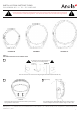
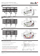
Connection – colour coding
WIRE
POWER
CONNECTION
WIRE
DATA
CONNECTION
Black L Red Data + (+)
White N Orange Data - (-)
Green/Yellow Blue Data 0V (0)
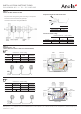
Connection – colour coding
WIRE
POWER
CONNECTION
WIRE
DATA
CONNECTION
Black L Red Data + (+)
White N Orange Data - (-)
Green/Yellow Blue Data 0V (0)
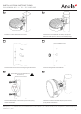
B
WIRELESS DMX - each xture
C
WIRELESS DMX - rst xture
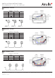
D
DMX or ETHERNET via E-Box
Connection – colour coding
WIRE
POWER
CONNECTION
WIRE
DATA
CONNECTION
Black L Red Data + (+)
White N Orange Data - (-)
Green/Yellow Blue Data 0V (0)
next
Junction Box
Calumma
Power
Junction Box
next
Junction Box
Calumma
Power
Junction Box
next
Junction Box
Calumma
Power
Junction Box
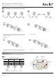
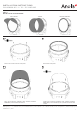
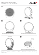
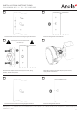
STEP 4
CABLE GLAND INSTALLATION
Assemble the cable gland according to the picture.
Use wrench size 22 for cable gland M20x1.5
Install Cable glands individually!
We recommend to apply an adequate layer of the paste
LOCTITE 5331 on the plastic holder of the cable gland before
inserting in into the body of the gland and an adequate layer of
the paste LOCTITE 577 on the thread of the gland body.
Failure to properly install cable glands will result in failure of
the water tight seal!