
User Manual


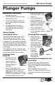
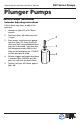

Plunger Pumps
Operating Instructions and Parts Manual RSV Series Pumps
First Choice When Quality Matters
NORTH
AMERICA
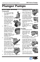
seal (Make sure it
is squarely seated).
(See Figure 21)
4. Installing the low-
pressure seal You
want the open side of the
seal to be pointed toward
the water side of the head (toward
the high-pressure seal) and the flat
side toward the drive end of the
pump.
Place the seal into
the gland at an
angle, with your
finger push the
exposed side of the
seal towards the center
and work the seal into position.
After the seal is in the gland you
can work it into it proper position..
(See Figure 22)
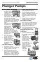
5. Install the retainer
O-ring. (See Figure 23)
6. Squarely seat the
retainer into the head
and push with even
pressure until it snaps
into position. (See
Figure 24)
Inlet Valve Removal:
1. Remove the valve cap.
2. Inspect the valve cap O-ring for any
damage, replace if necessary.
3. Screw the machine screw into
the hole on top of the valve cage
(approx 1/8”). Using the diagonal
pliers grasp the screw at the lowest
reachable point. Using the pump
head as a base, push down on the
pliers, the valve will lift out.
4. Use a small probe to move the
poppet up and down to assure that
the valve is functioning properly
and that no debris is stuck in the
valve.
5. Inspect the valve o-ring for any
damage, replace if necessary.
Inlet Valve Assembly:
1. Insert the valve assembly squarely
into the port pushing it into place
with a deap well socket (you will
feel the valve assembly seat).
3. Install the valve cap and torque to
the proper specification.
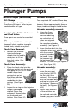
Pump Head to Drive End
Installation
1. Turn the crankshaft to align
the plungers as shown. (See
Figure 25)
2. Place the head
evenly onto the
plungers and push
it until it makes
contact with the
drive end of the
pump. (See Figure 26)
3. Torque the head
bolt as shown in the
tightening sequence
diagram.
(See Figure
27 & 28)
Figure 21
Figure 23
Figure 24
Service Pumps (continued)
Figure 22
Figure 25
Figure 26
Figure 27
Figure 28