
User`s manual
User’s Manual of TC Series Cutting Plotter
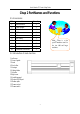
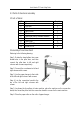
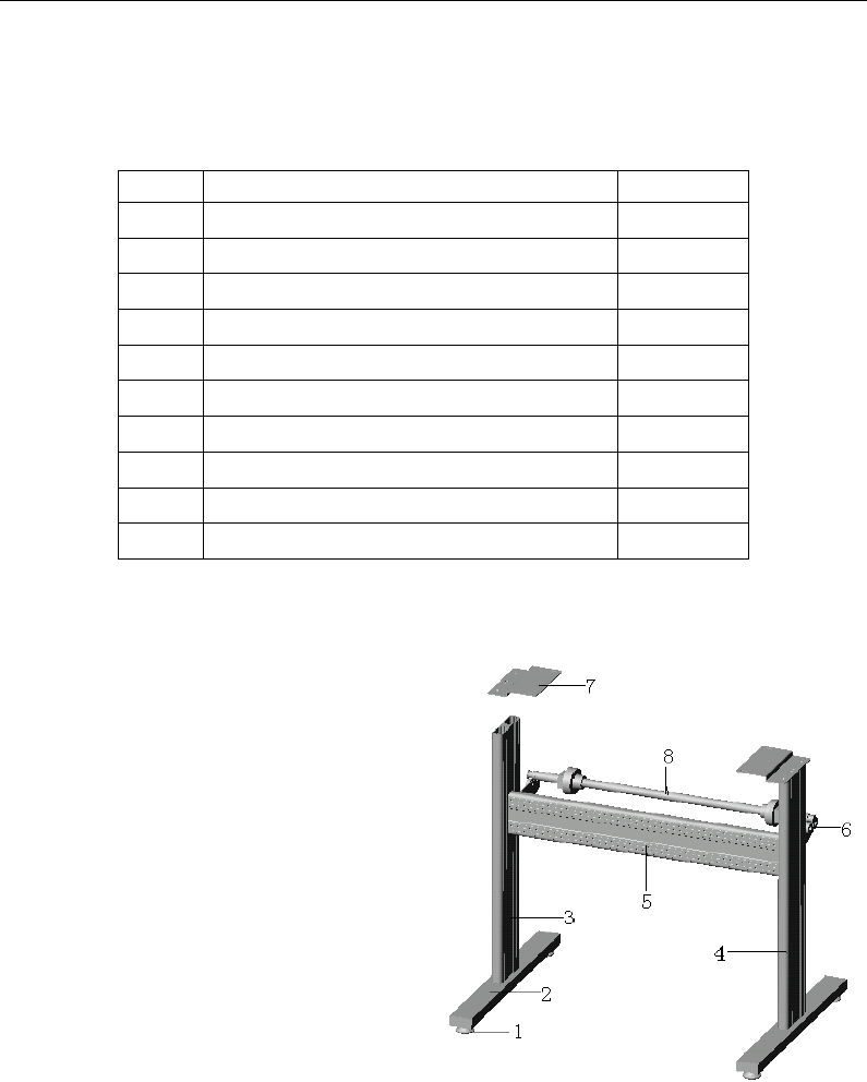
2-3 Parts of stand and assembly
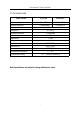
1 Parts of stand
NO. Item Quantity
1 Pillars 4
2 Pillar-bars 2
3 Left column 1
4 Right column 1
5 Crossbeam 1
6 Paper-hold roller of variable distance 2
7 Connection board 2
8 Paper roller 2
9
Screw M4×20
24
10
Screw M4×8
8
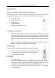
2 Assembly of machine stand
Referring to the following drawing:
Step 1: Rotate the stand pillars into screw
thread-holes in the pillar bars, and then
connect the pillar bars to left and right
columns with screws respectively.
Step 2: Connect the crossbeam to left and
right columns with screws.
Step 3: Join the paper hanger to the inside
of the left and right columns with screws.
Step 4: Join the connection board to the
top of the left and right columns with
screws.
Step 5: Lay down the four pillars of main machine, place the machine on the connection
board, then insert the pillars into the connection board to connect to the main machine.
Step 6: Place the paper-roller on the roller of paper hanger.
5