Datacryptor® Ethernet User Manual 1270A450-005 June 2008
Datacryptor Ethernet User Manual Page 2 Preface THALES
Datacryptor Ethernet User Manual Preface Contents 1 Preface............................................................................................................................................5 Trademark Acknowledgements ............................................................. 5 Revision Status....................................................................................... 5 License Agreement and General Information .............................................. 6 Security Advisory ....
Preface Datacryptor Ethernet User Manual Configure Dialog ...................................................................................... 43 Key Manager............................................................................................. 46 To commission a unit with the Commission button ................................. 46 Step 1: Installing a new Certificate Authority (CA)................................ 48 Step 2: Installing the authenticating CA:..........................................
Datacryptor Ethernet User Manual Preface 1 Preface Trademark Acknowledgements Datacryptor is a trademark of Thales e-Security. Microsoft Windows® XP and Windows® 2003 are registered trademarks of Microsoft Corporation. All other logos and product names are trademarks or registered trademarks of their respective companies. ©2006-2008 Thales e-Security. All rights reserved. Copyright in this document is the property of Thales e-Security.
Preface Datacryptor Ethernet User Manual License Agreement and General Information THALES e-SECURITY LTD. ("THALES") COMPUTER PROGRAM LICENSE AGREEMENT YOU SHOULD CAREFULLY READ THE FOLLOWING TERMS AND CONDITIONS OF THIS LICENSE AGREEMENT (the "AGREEMENT"). FOR PURPOSES OF THIS AGREEMENT, “SOFTWARE” IS DEFINED TO INCLUDE COMPUTER PROGRAMS INTENDED TO BE RUN ON A WORK STATION, PC, OR SIMILAR MACHINE, AND INCLUDES THE CD-ROM OR OTHER MEDIA ON WHICH THE SOFTWARE IS CONTAINED.
Datacryptor Ethernet User Manual Preface LIMITED WARRANTY The following limited warranty applies only to the Software and/or Firmware licensed hereunder. The hardware Machine is warranted pursuant to a separate Warranty set forth in the Machine documentation. The Machine documentation is contained on the CD-ROM, if any.
Preface Datacryptor Ethernet User Manual The government agrees that it shall be bound by the terms and conditions of this license agreement, to the maximum extent possible under federal law. This license agreement, and the governments assent hereto, supersedes any contrary terms or conditions in other contract documents (such as any statement of work).
Datacryptor Ethernet User Manual Preface Security Advisory This unit is being shipped with a Universal Certificate Authority that is to be used for demonstration purposes only. USE OF THE DEVICE, AS INITIALLY CONFIGURED, IN AN OPERATIONAL ENVIRONMENT IS NOT RECOMMENDED. THALES e-SECURITY EXPRESSLY DISCLAIMS ANY AND ALL LIABILITY FOR DAMAGES, INCLUDING BUT NOT LIMITED TO CONSEQUENTIAL DAMAGES, RESULTING FROM USE OF THE UNIVERSAL CERTIFICATE OR ANY OTHER CERTIFICATE SUPPLIED BY THALES e-SECURITY.
Preface Datacryptor Ethernet User Manual Contact Information SALES OFFICES Americas Europe, Middle East, Africa THALES e-Security, INC THALES e-Security LTD 2200 North Commerce Parkway Suite 200 Weston, Florida 33326 U.S.A. Tel: +1 954 888 6200 Fax: +1 954 888 6211 Toll free within USA: +1 888 744 4976 e-mail: sales@thalesesec.com Meadow View House Long Crendon Aylesbury Buckinghamshire HP18 9EQ England Tel: +44 (0)1844 201800 Fax: +44 (0)1844 208550 e-mail: emea.sales@thales-esecurity.
Datacryptor Ethernet User Manual About This Document 2 About This Document Viewing this document in Adobe Acrobat PDF Viewer It is recommended that this PDF document is viewed at 100% size with text smoothing adjusted to suit your monitor. The viewing size is easily adjusted by the use of the Zoom toolbar; you may set 100% size, or simply click the Actual Size icon: Viewing at 100% will provide the best appearance of the images in this document.
About This Document Datacryptor Ethernet User Manual This manual is organized into the following sections: Overview provides general information on the hardware and software. Background Information provides a brief introduction to the device and Ethernet Layer 2 technology and terminology. Installation describes how to install the Datacryptor Ethernet hardware and Element Manager Software.
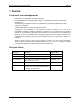
Datacryptor Ethernet User Manual Overview 3 Overview The Thales Datacryptor Ethernet is a high speed, high bandwidth, integrated security appliance. The three models provide different transfer speeds; the 100 Mb Ethernet provides 100 Mbps, while the 1 Gig and 10 Gig Ethernet units offer encryption at Gigabit Ethernet Layer 2 transfer rates.
Overview Datacryptor Ethernet User Manual Figure 3-3: Thales Datacryptor 1 Gig Ethernet Front Panel Figure 3-4: Datacryptor 1 Gig Ethernet Rear Panel Figure 3-5: Thales Datacryptor 10 Gig Ethernet Front Panel Figure 3-6: Datacryptor 10 Gig Ethernet Rear Panel Note: Page 14 See The Front Panel LEDs in the Element Manager Reference section for full information on the LED indicators.
Datacryptor Ethernet User Manual Overview Product Features Installation • Mount in any standard 19” rack Key management • Diffie-Hellman key exchange or on a tabletop Interfaces • The 100 Mb Ethernet has two (groups 1, 2, and 5) Encryption • Advanced Encryption Standard RJ45 sockets for connecting to the Host and Network circuits • The 1 Gig Ethernet and 10 Gig Ethernet units have two SFP or XFP sockets which accept a range of transceiver modules for the encrypting and decrypting of network traffic
Overview Datacryptor Ethernet User Manual Element Manager The Element Manager application provides a secure way to configure, manage, and upgrade the Datacryptor Ethernet. The program runs under various versions of Microsoft Windows operating systems. Please see the Software Requirements for a more detailed description of the environment required. The PC can connect to a Datacryptor Ethernet unit to manage it using the IP protocol over a standard 10/100 Ethernet connection.
Datacryptor Ethernet User Manual Background Information 4 Background Information Datacryptor Ethernet Unit The Thales Datacryptor Ethernet units are high performance, integrated security appliances that provide encryption at high line speeds. The 1 Gig and 10 Gig Ethernet units operate at optical line speeds and have the added advantage that they can, over limited distances, use copper media.
Background Information Datacryptor Ethernet User Manual Authenticate Management Data - The Datacryptor Ethernet uses the HMAC keyed hash variant of the SHA-1(Secure Hash Algorithm) to authenticate management data using SNMP v3. Security Terms Diffie-Hellman – Diffie-Hellman is a method for key exchange that allows two autonomous systems to exchange a secret key over an untrusted network without prior secrets.
Datacryptor Ethernet User Manual Installation 5 Installation This section will detail the installation of the hardware and software. Hardware installation is discussed first. Hardware Installation There are four steps in installing the unit: • Unpack the Shipping Carton • Mount the Unit • Connect the Cables • Power on the Datacryptor Unpack the Shipping Carton Remove all product components from the shipping carton and compare the contents to the packing list.
Installation Datacryptor Ethernet User Manual Airflow Make sure that there is sufficient flow of air around the Datacryptor so that safe operation is not compromised. Maintain a clearance of at least 3 inches (7.62 cm) at the sides of the Datacryptor to ensure adequate air intake and exhaust. If installing in an enclosed rack, make sure the rack has adequate ventilation or an exhaust fan.
Datacryptor Ethernet User Manual Installation Port Cabling Supplied By Network and Host Port For the 100 Mb Ethernet unit: Category 5 or above RJ-45 connector. For the 1 Gig and 10 Gig Ethernet units: Dependant on Customer the SFPs or XFPs ordered with the unit. The options are Category 5 or above RJ 45 connector. 850nm Multi-mode fiber. 1310nm or 1550nm Single mode fiber. 10/100 Ethernet Management Port Shielded Category 5 straight through cable (STP), RJ-45 connector.
Installation Datacryptor Ethernet User Manual Figure 5-1: Datacryptor Panel Connectors (The 100 Mb Ethernet unit’s management ports are located on the front panel) WARNING: (1 Gig and 10 Gig Ethernet units only) Infra-red radiation is emitted from aperture ports of single mode or multi-mode transceivers when no cable is connected. Avoid exposure and do not stare into the open apertures. Apertures should be covered when not in use.
Datacryptor Ethernet User Manual Installation 4. On the Datacryptor’s rear panel, plug the power cords into the power receptacles. Attach the opposite ends to a power source. The power LED illuminates when the unit is powered up. The Diagnostic Boot sequence allows the LEDs to be checked and the unit type to be verified. The sequence follows this pattern: Network Error Loopback Alarm Encrypt Plain Host Unit Type − All LEDs on for one second.
Installation Datacryptor Ethernet User Manual • The PC must have a pointing device (mouse), a CD ROM drive, a free serial port, and at least 228 Mb hard disk space (for the software and data files). If you want to install the Adobe Acrobat reader (included on the CD to view the manuals) this will require a further 10 MB of hard disk space. • The user should ensure that there is at least 5Mb of memory for each copy of the Front Panel Viewer being run concurrently.
Datacryptor Ethernet User Manual Connecting to Datacryptor Ethernet Units 6 Connecting to Datacryptor Ethernet Units There are three methods of connecting to the Datacryptor Ethernet units: Element Manager, serial connection to CLI, and SNMP. The Element Manager GUI application is used to manage and configure the Datacryptor Ethernet device(s). It connects to the Datacryptor via the 10/100 Ethernet Management port.
Connecting to Datacryptor Ethernet Units Datacryptor Ethernet User Manual 2. Open a terminal session through a VT-100 terminal emulation program such as HyperTerminal. Enter the connection name, the appropriate serial port (usually COM1 or COM2), and the following serial port parameters: Serial Port Parameter Value Baud Speed 115,200 Parity None Data Bits 8 Stop Bits 1 Flow Control None 3. Switch on the Datacryptor unit. 4.
Datacryptor Ethernet User Manual Connecting to Datacryptor Ethernet Units 7. At the IPCONFIG> prompt, type: SET where: identifies the port to be set and is one of the following: − NETWORK (public network port), − CONTROL (serial control port), − ETHERNET (Ethernet management port). is IP address of a subnet to be added or deleted. is netmask of the subnet. Examples Set Control 2.2.2.2 255.255.0.
Connecting to Datacryptor Ethernet Units Datacryptor Ethernet User Manual 5. Click on the shortcut to launch the connection. 6. Select the Properties button. 7. On the General tab confirm correct connection. 8. Click Configure button and use the menu to set the maximum connection speed of 115200 bps. Set the flow control to none; the Ethernet and SONET do not support flow control. 9. On the Network tab, select TCP/IP and click Properties - enter the address 2.2.2.1. 10.
Datacryptor Ethernet User Manual Connecting to Datacryptor Ethernet Units 4. Select the unit type as Datacryptor and enter the IP address of the Datacryptor Ethernet unit. Press Enter or select Next to continue.
Connecting to Datacryptor Ethernet Units Datacryptor Ethernet User Manual 5. Select the connection type for the Datacryptor Ethernet unit; press Enter or click on Next to continue. 6. The application will attempt to connect to the specified IP address and - if successful display the unit's Unit Name by way of confirmation, as above. Type a descriptive name for the connection in the edit box (this will be shown in the main window below its icon). 7.
Datacryptor Ethernet User Manual Connecting to Datacryptor Ethernet Units 8. Now, double-click on the new Datacryptor icon to connect to it. A splash screen will be displayed whilst connecting to the unit and within a minute this should display the Front Panel Viewer for the unit - an example for the 100 Mb Ethernet Datacryptor is given below. It is possible to abort the connection attempt at the splash screen by pressing its Cancel button: 9.
Connecting to Datacryptor Ethernet Units Datacryptor Ethernet User Manual 10. You can login to it by using the Login button, and manage it by using the View Logs, Properties and License Management buttons. The management facilities are described in Element Manager Reference section below. To configure the unit for your network setup, select the Properties button to display the unit's properties, and select the appropriate tabs.
Datacryptor Ethernet User Manual Connecting to Datacryptor Ethernet Units This provides a mechanism for another application (e.g. an SNMP network manager) to invoke the Front Panel Viewer for a specified Datacryptor unit. If Dc2k.exe is invoked without any parameters, it will prompt the user to enter the IP address of the unit to connect to. To display a short summary of the command line parameters supported, use the command: Dc2k.
Element Manager Reference Datacryptor Ethernet User Manual 7 Element Manager Reference The Element Manager consists of the following components: • The Main Window • The Front Panel Viewer • The Configure dialog • Key Manager • The Login dialog • The Change Password dialog • The Logs window • The Properties dialog Each will now be described in turn. Remember that you also have access to online help while using the Element Manager via the F1 (Help) key and the Help menu.
Datacryptor Ethernet User Manual Element Manager Reference Main Window Pull-down Menus The pull-down menus are: File, Edit, View, Tools and Help. File The following options are available from the File pull-down menu: Menu Option Description New Unit Add a new Datacryptor unit to the window. Delete Unit Delete the selected Datacryptor unit from the window. Exit Terminate the application, closing all sessions that may be open.
Element Manager Reference Datacryptor Ethernet User Manual Tools The following options are available from the Tools pull-down menu: Menu Option Description View Audit Log Display an audit log of all changes made using the Element Manager. Dial-Up Networking Launches the operating system's Dial-Up Networking application, to manage dial up connection details or make a connection. Poll Network Units Poll all Datacryptor units connected via the network.
Datacryptor Ethernet User Manual Element Manager Reference To connect to a Datacryptor unit: 1. Double-click its icon. 2. Once the connection has been made, the Front Panel Viewer will be displayed showing information read from the unit. This dialog provides access to all the Datacryptor unit management facilities described throughout this guide. 3. To disconnect from the Datacryptor unit, click the Close button in its Front Panel Viewer.
Element Manager Reference Datacryptor Ethernet User Manual Front Panel Viewer A splash screen is displayed when you attempt to connect to a Datacryptor Ethernet unit. This process should normally complete within a few seconds but might take up to one minute. You can abort the connection attempt from the splash screen by pressing its Cancel button. Note that the text on the splash screen may change from "Identifying unit" to "Fetching unit information" during the connection process.
Datacryptor Ethernet User Manual Element Manager Reference 100 Mb Ethernet Front Panel Viewer 1 Gig Ethernet Front Panel Viewer 1270A450-005 - June 2008 Page 39
Element Manager Reference Datacryptor Ethernet User Manual 10 Gig Ethernet Front Panel Viewer The management facilities are provided by the View Logs and Properties buttons. If View Logs or the Properties buttons are grayed out, they are inaccessible because you haven't logged in yet - use the Login button to do so. Once you have logged in, the Login button changes to Logout.
Datacryptor Ethernet User Manual Element Manager Reference • Beneath the front panel diagram are five large buttons that provide direct access to management facilities (see the Front Panel Viewer buttons section below). Note: Pressing F5 while using the Front Panel Viewer will cause a refresh of all displayed settings from the unit. User Key Material Adminv2.usr User key material (containing public and secret keys of user) protected by a default password of: PASSWORD Adminv3.
Element Manager Reference Datacryptor Ethernet User Manual Fast Flash Link Down Slow Flash Not used Off Loss of Signal, Loss of Synchronization The Front Panel Viewer buttons The buttons in the Front Panel Viewer are the same for all models of Ethernet Datacryptor; they provide access to the management facilities, as follows: • Login: This button is only enabled if you have not logged in yet.
Datacryptor Ethernet User Manual Element Manager Reference • Help: The Help button launches the help application displaying the help file for the dialog. • Close: The Close button closes the Front Panel Viewer. Configure Dialog This dialog is displayed when you select the Configure button from the Front Panel Viewer. It provides configuration of the rules that the Front Panel Viewer will enforce in support of the security policy.
Element Manager Reference Datacryptor Ethernet User Manual Extended files, including those that have been automatically upgraded, should not be used in previous versions of the Front Panel Viewer as that could make them unusable in this current version. Minimum Password Length The Front Panel Viewer will require that any new password entered is at least this length.
Datacryptor Ethernet User Manual Element Manager Reference The user will be blocked from further attempts for this time. Once the block time has expired the user will again be allowed to attempt to log in. Inactivity Time The Front Panel Viewer can automatically log off a user if it has seen no mouse or keyboard activity for a time. Set this field to the maximum inactivity time, in seconds.
Element Manager Reference Datacryptor Ethernet User Manual When the directory is set to read-only the Front Panel Viewer will disable the Configure button. Key Manager As previously stated when the Datacryptor Ethernet unit is supplied from the Manufacturer, Thales e-Security provides the CA that is loaded. When first commissioned the unit may require testing and the Universal CA provided on the Datacryptor Element Manager CD-ROM can be used.
Datacryptor Ethernet User Manual Element Manager Reference 2. Click the Commission button at the top of the dialog. This will start the Commissioning Wizard, which begins by displaying an overview of the process as shown below: The first item in the list will be Installing a Certificate Authority (CA) as shown above. 3. Click the Next button to proceed to step 1 below. The first page of the wizard asks if a new CA is to be installed in the unit.
Element Manager Reference Datacryptor Ethernet User Manual Step 1: Installing a new Certificate Authority (CA) Units are normally delivered under the control of the manufacturer CA (DC2K Manufacturer), with the Universal CA available on disk; this dialog allows you to transfer control to a different custom CA: 1. To stay under the control of the manufacturer CA, select the No option and click the Next button or press Enter. This will take you to step 3. 2.
Datacryptor Ethernet User Manual Element Manager Reference Step 2: Installing the authenticating CA: Insert the diskette containing the authenticating CA's .CA file and enter the path to the .CA file (or use the Browse button to find it). Click the Next button to proceed to step 3.
Element Manager Reference Datacryptor Ethernet User Manual Step 3: Setting the unit name: Each Datacryptor Ethernet unit within a User Group must have a different name. You can either leave the unit name as delivered (since units are manufactured with unique names – the same as the serial number) or change it now, according to your security procedures. The edit box displays the unit's current unit name. 1. To keep the displayed unit name, click Next. 2.
Datacryptor Ethernet User Manual Element Manager Reference Step 4: Generating a Certificate: 1. Enter the path to the .DHP File (Diffie-Hellman Parameters), or use the Browse button to select it. 2. Specify the dates between which the Certificate is valid in the Effective Date (start) and Expiration Date (finish) fields. The Start Time is effectively 00:00 and the End Time is 23:59 (unless the issuing CA is different) on the days selected. The default end date is the last day of the issuing CA 3.
Element Manager Reference Datacryptor Ethernet User Manual 1. Click Finish to begin the commissioning process, which will take a few seconds. 2. When commissioning has completed, confirm that the Datacryptor unit's LEDs are flashing (which indicates that the unit has been commissioned successfully). Check the unit's LEDs (or get someone else to do so, if the unit is remote) and click Yes if they are flashing. 3. The new CA and certificate can be seen in the Certificates tab of the Key Manager. 4.
Datacryptor Ethernet User Manual Element Manager Reference Login Dialog This dialog is displayed when you select the Login button from the Front Panel Viewer, to login to gain access to the unit management facilities. Enter the password into the login dialog and either click the OK button or press Enter. You can also use the Change Password button to change your password - providing you know the original password.
Element Manager Reference Datacryptor Ethernet User Manual CAUTION: If the password is lost all Administrator functionality is lost, including the ability to assign a new password. The only means of resetting the password is to the restore the factory settings on the device (please call Customer Service for support). This operation overwrites all previously saved configurations, policies, and keys with factory defaults.
Datacryptor Ethernet User Manual Element Manager Reference • Trace: A report of internal software conditions detected by the unit, these are not hardware errors but may help support personnel understand unusual operational conditions. They appear on the display as ‘Internal Error’ but, when saved to disk as a text file, the text is expanded. When seen, these should be reported to the Support department at Thales e-Security for investigation. Note: New errors will cause the Error LED to flash.
Element Manager Reference Datacryptor Ethernet User Manual Properties Dialog The Properties dialog is displayed when you select the Properties button in the Front Panel Viewer. The image shown on the dialog will reflect the model of Ethernet Datacryptor that you are using. You use the dialog to examine and change the properties of the selected unit. These properties are organized into a number of separate tabs.
Datacryptor Ethernet User Manual Element Manager Reference Each of the tabs will now be described in turn. The General Tab The properties on the General tab control the general behavior of the unit. The image shown on the General tab will reflect the model of Ethernet Datacryptor that you are using. Unit Name: read from the unit. Description: read from the unit. Change: click this button to set the unit's clock/calendar.
Element Manager Reference Datacryptor Ethernet User Manual Cable detected: the types of cable connected to the unit. Save: stores the current properties in a named file, which can then be loaded using the Load button (for example, to restore the settings after a unit has been reset to factory defaults). Load: loads saved properties from a named file. You can then examine, edit or save them, or apply them to the current unit by clicking the Apply button.
Datacryptor Ethernet User Manual Element Manager Reference The Diagnostics Tab The Diagnostics tab will provide a range of diagnostic aids. Currently, it provides two diagnostic facilities: Reboot: click this button to reboot the unit as if it had been turned off and on again. (This operation takes several minutes) Rebooting halts all operations on the device and starts the boot process in the same manner as when the power is cycled. Save any configuration changes prior to rebooting the unit.
Element Manager Reference Datacryptor Ethernet User Manual CAUTION: Rebooting the device interrupts the data traffic on the Host and Network ports. Erase: click this button to erase the unit’s Key material. Basic unit Configuration will not be lost, i.e. the unit can still be managed remotely once the unit has re-booted. The following confirmation dialog will be shown. Click on Yes to continue.
Datacryptor Ethernet User Manual Note: Element Manager Reference The loopback mode is regarded as a transient feature intended purely as an aid to troubleshooting. Therefore when the unit is rebooted the loopback options are set to Disabled. The IP Management Tab The properties on the IP Management tab control the IP addressing of the unit.
Element Manager Reference Datacryptor Ethernet User Manual Configuring SNMP Datacryptor units record all significant management and error events in their logs for later examination, but can also be configured to report them immediately to a central location, by using the SNMP protocol - to help centralize and simplify management. Events are reported as SNMP Traps V1, v2c, or v3 (as selected on the Traps tab – see below), to a central device (typically a PC) called an SNMP Network Manager.
Datacryptor Ethernet User Manual Element Manager Reference − Enter the Location and Contact information for this unit. Both edit boxes accept spaces and alphanumeric characters. There is a limit of 255 characters for each field. − Select which versions of SNMP are to be supported using the Enable SNMP tick boxes.
Element Manager Reference Datacryptor Ethernet User Manual 5. Click OK to add the community. To edit an SNMP community: Select the entry to edit by clicking on it, and then click the Edit button. To delete an SNMP community: Select the entry to delete by clicking on it, and then click the Delete button. SNMPv3 Users SNMP Version 3 supports an access control model based upon users and views. Management of these users and views is controlled using native SNMPv3 commands.
Datacryptor Ethernet User Manual Element Manager Reference Traps Tab The Traps tab lists the details of each SNMP trap that has been defined for this unit, and provides facilities to maintain the list: To enable or disable SNMP traps for this unit, use the appropriate Enable checkboxes for the each version of SNMP.
Element Manager Reference Datacryptor Ethernet User Manual − Trap Address: Type the IP address of the SNMP trap manager. − Community: This field is unused because the unit only issues SNMP Version 3 traps. You can set this field to any value without affecting behavior of trap issuance. − Trap Filter: Tick the categories of event to send to this trap manager. Note: Page 66 It may take up to 20 seconds to acknowledge the selected action.
Datacryptor Ethernet User Manual Element Manager Reference Adding SNMPv3 Trap Managers: When using SNMPv3 you are able to specify whether the reports will use authentication alone, or authentication and privacy combined, or no security at all. Add Trap Manager dialog for SNMPv3 − Security Type: Select the type of security that will be used for the reports from the drop down list.
Element Manager Reference Page 68 Datacryptor Ethernet User Manual THALES
Datacryptor Ethernet User Manual Element Manager Reference To edit an SNMP trap manager: 1. Select the entry to edit by clicking on it, and then click the Edit button. 2. Edit the entries in the Edit Trap Manager dialog as required, and then click OK. Note: It may take up to 20 seconds to acknowledge the selected action. To delete an SNMP trap manager: 1. Select the entry to delete by clicking on it, and then click the Delete button. 2. Click Yes to confirm deletion, or No to cancel deletion.
Element Manager Reference Datacryptor Ethernet User Manual IP Route Config Selecting this button on the Properties - IP Management tab will display the IP routes dialog detailing the IP routes that have been defined for this unit and providing facilities to maintain the IP routes list: Use the Add, Edit and Delete buttons to manage the required list of IP routes.
Datacryptor Ethernet User Manual Element Manager Reference The Security Tab The properties on the Security tab control crucial aspects of the security of the Datacryptor unit. They are as follows: • KEK: the longest time that the unit will use a KEK for, in days, hours, minutes. • DEK: the longest time that the unit will use a DEK for, in days, hours, minutes – or the time at which to perform a daily key exchange (see next control).
Element Manager Reference Datacryptor Ethernet User Manual • Disable Key Exchanges: check this box to disable all key exchanges other than those required to make a secure connection. (This disables the previous 4 controls until you uncheck it.) • Retry every minute - with this box checked the Datacryptor Ethernet will try to poll for lost peers every minute, this is the default behavior.
Datacryptor Ethernet User Manual Element Manager Reference The RIP Tab The RIP tab sets up the properties of the Routing Information Protocol (RIP) and configures the way Rip messages are sent to other routers. The Datacryptor Ethernet supports versions RIP-1 and RIP-2. RIP Compatibility This set of radio buttons is used to select which version of RIP that the Datacryptor Ethernet is using: • Off - this switches off compatibility with any version of RIP. No RIP messages transmitted on any port.
Element Manager Reference Datacryptor Ethernet User Manual • RIP 2 (broadcast) - this sets the Datacryptor to be compatible with RIP version 2 but uses the broadcast mode. Some networks that are using RIP 1 may want to use RIP 2 but not use multicast transmissions. This will ensure that RIP responses are not addressed to multicast address 224.0.0.9. Note: IGMP is not needed since these are inter-route messages that are not forwarded.
Datacryptor Ethernet User Manual Element Manager Reference The Ethernet Comm Tab for 1 and 10 Gigabit Datacryptors The properties on the Ethernet Comm tab control the communications settings of the Datacryptor unit. The Comm tab illustrated in this section applies to the 1 Gig Ethernet unit. Differences between the 1 Gig and 10 Gig units will be stated where relevant. Ethernet Comm Tab for the 1 Gigabit Datacryptor The properties are as follows: Mode- Selects one of two options for the transmission mode.
Element Manager Reference Datacryptor Ethernet User Manual The unit can be rebooted using the option available on the Diagnostic tab Interface Mode - Allows the Host and network interfaces to be switched Up/Down. Laser Mode - Allows the Host and network Lasers to be individually switched On/Off. Pause - The Pause option is a special Ethernet function that provides flow control between Ethernet devices.
Datacryptor Ethernet User Manual Element Manager Reference The Ethernet Comm Tab for 100 Mb Datacryptor The properties on the Ethernet Comm tab control the communications settings of the Datacryptor unit. They are as follows: Mode- Selects one of two options for the transmission mode. − Bulk - Unit encrypts everything including Ethernet header. − Tunneling - Unit encrypts every thing below Ethernet header.
Element Manager Reference Datacryptor Ethernet User Manual The unit can be rebooted using the option available on the Diagnostic tab Interface Mode - Allows the Host and network interfaces to be switched Up/Down. Link Mode - Allows the Host and network connections to be individually switched On/Off. If the LLCF option is selected, the connection is on with link loss carry forward turned on. Auto Negotiation - allows the unit to automatically negotiate connection without intervention from the user.
Datacryptor Ethernet User Manual Element Manager Reference The Ethernet Encryption Tab The Ethernet Encryption tab shows the Current Encryption mode in use by the unit. Target Encryption mode: This allows you to select the target or required encryption mode using the drop down menu. The three options are: Standby, Encrypt, or Plain. Peer Details: The Peer unit’s details (Name, IP Address, etc) are shown on the tab.
Element Manager Reference Datacryptor Ethernet User Manual The Expert Tab The Ethernet Expert tab allows to Enable CTS Mode. The Ethernet Expert tab is not shown when using the 10Gig Ethernet unit since CTS mode is always enabled for the 10Gig Ethernet unit. The CipherText Stealing mode minimizes the latency caused by the encryption of the Ethernet packets.
Datacryptor Ethernet User Manual Element Manager Reference The Ethernet Tunneling Tab The Ethernet Tunneling tab will only be present when Tunneling mode is selected on the Ethernet Comm tab. Note: The Tunneling Settings section, which includes the Fragmentation Size item, is not displayed for the 10Gig Ethernet unit. The 10Gig Ethernet unit does not support fragmentation.
Element Manager Reference Datacryptor Ethernet User Manual This is entered by selecting the Change button, the following dialog is shown. Enter the required address in the boxes shown. Movement between the boxes can be achieved by using the mouse or the tab and shift tab key combinations. The units MAC address must be inserted in the peer unit address box at the other end of the link.
Datacryptor Ethernet User Manual Element Manager Reference This gives the option of setting a maximum of four rules on both the Host to Network and Network to Host ports. Selecting the New Rule button will open the Filter Rule dialog. When setting a rule, the first step is to select a rule type: Rule Type • Plain this allows the Datacryptor unit to pass information from the specified addresses in plain, and is used to allow network specific traffic.
Element Manager Reference Datacryptor Ethernet User Manual MAC Address The destination and source addresses are standard MAC addresses with the added option of using the *wildcard character (see below) to enable a range of addresses to be identified. When you have set the addresses, select OK to add the new rule to the list. The apply button will then become active. The Edit and Delete functions requires the user to select a rule prior to clicking the appropriate button.
Datacryptor Ethernet User Manual Element Manager Reference The permissible range for Fragmentation Size is: • • Gigabit Ethernet: 0 = no fragmentation, 256 ≤ Fragmentation Size ≤ 16300 10/100 Mb Ethernet: 0 = no fragmentation, 256 ≤ Fragmentation Size ≤ 2000. The Environment Tab The Environment tab shows the fan speeds along with the unit temperature and power unit condition. These readings may be used to check that the Datacryptor environment is satisfactory for normal operation.
Appendix A: Device Maintenance Datacryptor Ethernet User Manual Appendices Appendix A: Device Maintenance Periodically perform maintenance on your Datacryptor. • • • • Keep components free of dust and other particulate matter. Check fans for reduced airflow caused by dust build-up and clean as necessary. Examine cables and fiber for damage and ensure that airflow requirements have been met.
Datacryptor Ethernet User Manual Appendix A: Device Maintenance a locked equipment closet provides a more secure environment than an open server room. At a minimum, we recommended that the unit’s physical integrity be checked monthly. The units also have interlock switches that will cause the key material to be erased if the lid is removed. Power Supplies Failure of one of the power supply units will cause a high-pitched continuous note to sound, allowing a replacement to be planned.
Appendix B: Loading Datacryptor Unit Software Datacryptor Ethernet User Manual Appendix B: Loading Datacryptor Unit Software Datacryptors are factory pre-loaded with the required ‘application’ software and protocol data. However, if a new version of software needs to be loaded into a Datacryptor, the following procedure describes how to carry out the operation using the Image Loader utility, which will be provided with the new version of software.
Datacryptor Ethernet User Manual Appendix B: Loading Datacryptor Unit Software 3. Select the COM port that the Datacryptor is connected to, using the pull down menu. This is COM1 by default. 4. If the Datacryptor application is already running, you may choose the Ethernet radio button. Enter the IP address in the field next to the Ethernet radio button. Ethernet is faster than Serial for loading code. 5.
Appendix B: Loading Datacryptor Unit Software Datacryptor Ethernet User Manual 4. The Image Loader may also perform other "housekeeping" tasks such as generation of correct Ethernet address and IP addresses used by later software, if these are missing. If housekeeping tasks are performed, you will be notified in the Status Messages. 5. The baud rate at which the upload will take place is displayed, and the upload of the new application code will begin.
Datacryptor Ethernet User Manual Appendix B: Loading Datacryptor Unit Software Operations during Ethernet Code Loading The following operations are only applicable if you are using an Ethernet connection for loading. 1. The Image Loader will try to initialize communications with the Datacryptor.
Appendix B: Loading Datacryptor Unit Software Datacryptor Ethernet User Manual 2. Once the hardware has been validated, select the Image Loader file (.ilf file) containing the Datacryptor application image (e.g. dc2k.ilf). Select the file and click OK.
Datacryptor Ethernet User Manual Appendix B: Loading Datacryptor Unit Software 3. Image Loader will begin uploading the code contained in the Image Loader file.
Appendix B: Loading Datacryptor Unit Software Datacryptor Ethernet User Manual Completing the Upload 1. Progress of the load is shown via the Upload Progress bar and you will be notified when this is finished. If ‘Save Log Events’ was selected, a dialog will now prompt you for the file name and location for saving the log file. 2. Upload of the application is complete, click Close to shut down the application, or connect another Datacryptor for loading. 3.
Datacryptor Ethernet User Manual Appendix C: Product Specifications Appendix C: Product Specifications System Specifications Interfaces - Host and network ports (see Appendix E for transceiver details used with the 1 Gig and 10 Gig Ethernet Datacryptors) - 10/100 Mbps auto-sensing LAN port - RS-232C port Electrical/Mechanical Dimensions 19 inch rack mount design 100-240 VAC, 10A, 50/60 Hz or -48 VDC 100 Mb Ethernet unit: 100M: 44 mm H x 483 mm W (including mounting brackets) x 240 mm D (including conne
Appendix D: Environmental & Regulatory Datacryptor Ethernet User Manual Appendix D: Environmental & Regulatory Environmental Specifications Description Value Temperature 5-40 degrees C (40 to 104 degrees F) Humidity 10% to 90% at 25°C (77°F) non-condensing, failing to 50% maximum at 40°C (100°F) Altitude -200 - 10,000 feet AMSL operating altitude Regulatory Safety/Emissions/Immunity IEC 60950, 3rd Edition (1999) Underwriter Labs Safety CSA-C22.
Datacryptor Ethernet User Manual Appendix D: Environmental & Regulatory Interference-Causing Equipment Standard Compliance Notice (Canada) "This Class B digital apparatus meets all requirements of the Canadian-interference causing Regulations." Cet appareil numérique de la classe B est respecte toutes les exigences du Règlement sur le matériel du Canada.
Appendix E: SFP and XFP Interfaces Datacryptor Ethernet User Manual Appendix E: SFP and XFP Interfaces The Datacryptor 1 Gig Ethernet unit is supplied with Small Form Factor Pluggable (SFP) interfaces (see above), using single-mode fiber or multi-mode fiber (MM SPF), as specified at the time of ordering. The 10 Gig Ethernet unit is supplied with 10 Gigabit Small Form Factor Pluggable (XFP) single-mode fiber laser devices (see below), as specified at the time of ordering.
Datacryptor Ethernet User Manual Appendix F: Preventing Electrostatic Discharge Appendix F: Preventing Electrostatic Discharge Electrostatic discharge (ESD) can damage electronic components and equipment. ESD occurs when electronic components are improperly handled and can result in complete or intermittent failures. Always follow ESD-prevention procedures when removing and replacing components.
Appendix G: Troubleshooting Datacryptor Ethernet User Manual Appendix G: Troubleshooting This appendix is provided to aid you in determining basic problems with your Thales Datacryptor Ethernet unit. If you cannot resolve the problem using this troubleshooting guide, please contact Thales customer support. Possible Problems and Solutions The troubleshooting information in this section is grouped into the following categories: logging in, configuration and traffic flow.
Datacryptor Ethernet User Manual Cannot establish a link Appendix G: Troubleshooting Check physical connectivity to ensure proper signal path. If using a 1 Gig or 10 Gig Ethernet Datacryptor, verify that compatible SFPs and fiber type is being used for connectivity. Use the loopback mode to test the connections, see The Diagnostics Tab on page 59.
Appendix H: SNMP MIB Support Datacryptor Ethernet User Manual Appendix H: SNMP MIB Support In order to support organizations who utilize SNMP to monitor network devices and status, the Datacryptor Ethernet product does provide a Simple Network Management Protocol Version 3 (SNMPv3) and Management Information Base II (MIB-II) interface. The SNMPv3 implementation is based upon RFCs 1157, 1901–1910, 2576, 2578 – 2580, and 3411–3418.
Datacryptor Ethernet User Manual Appendix H: SNMP MIB Support MIB Name Description DC2K-MIB-RFC1213 RFC 1213 defines the Management Information Base (MIB-II) for use with network management protocols in TCP/IP-based internets. The Datacryptor supports the majority of read-write attributes in this MIB as read-only in order to preserve the security of sensitive attributes.
Appendix H: SNMP MIB Support Datacryptor Ethernet User Manual MIB Name Description DC2K-MIB-RFC2863 RFC 2863 defines a portion of the Management Information Base (MIB-II). Specifically, it defines objects for the management of network interfaces. The Datacryptor supports the majority of read-write attributes in this MIB as read-only in order to preserve the security of sensitive attributes. Please see the supplied MIB file for specific details.
Datacryptor Ethernet User Manual Appendix I: Log and SNMP Trap Numbers Appendix I: Log and SNMP Trap Numbers The following table lists the log messages that may be viewed in the Datacryptor log and the corresponding SNMP trap messages that may be generated. The log/trap messages are listed in the Log type order Error, Key followed by Audit. The log number is the log number of the message when viewed in the logs by the Front Panel Viewer.
Appendix I: Log and SNMP Trap Numbers Datacryptor Ethernet User Manual Log Trap Errors Hardware Log Type Code Trap No. Severity Message Error (Hardware) 1 120 Critical Random no.
Datacryptor Ethernet User Manual Appendix I: Log and SNMP Trap Numbers Log Type Code Trap No. Severity Message Information Error (Hardware) 14 122 Major Alarm condition: movement alarm activated Unit recovered from alarm and noted movement alarm had been activated: it will be necessary to reboot the unit.
Appendix I: Log and SNMP Trap Numbers Datacryptor Ethernet User Manual Log Type Code Trap No.
Datacryptor Ethernet User Manual Appendix I: Log and SNMP Trap Numbers Log Type Code Trap No.
Appendix I: Log and SNMP Trap Numbers Datacryptor Ethernet User Manual Key Errors Log Type Code Trap No.
Datacryptor Ethernet User Manual Appendix I: Log and SNMP Trap Numbers Log Type Code Trap No.
Appendix I: Log and SNMP Trap Numbers Datacryptor Ethernet User Manual Log Type Code Trap No.
Datacryptor Ethernet User Manual Appendix I: Log and SNMP Trap Numbers Log Type Code Trap No.
Appendix I: Log and SNMP Trap Numbers Datacryptor Ethernet User Manual Log Type Code Trap No.
Datacryptor Ethernet User Manual Appendix I: Log and SNMP Trap Numbers Log Type Code Trap No.
Appendix I: Log and SNMP Trap Numbers Datacryptor Ethernet User Manual Log Type Code Trap No.
Datacryptor Ethernet User Manual Appendix I: Log and SNMP Trap Numbers Log Type Code Trap No.
Appendix I: Log and SNMP Trap Numbers Datacryptor Ethernet User Manual Log Type Code Trap No.
Datacryptor Ethernet User Manual Appendix I: Log and SNMP Trap Numbers Log Type Code Trap No.
Appendix I: Log and SNMP Trap Numbers Datacryptor Ethernet User Manual Log Type Code Trap No. Severity Message Information Key 2018 618 Minor No Encrypt channel is available The maximum number of encrypt slots has been reached.
Datacryptor Ethernet User Manual Appendix I: Log and SNMP Trap Numbers Log Type Code Trap No.
Appendix I: Log and SNMP Trap Numbers Datacryptor Ethernet User Manual Log Type Code Trap No.
Datacryptor Ethernet User Manual Appendix I: Log and SNMP Trap Numbers Audit Errors Log Type Code Trap No.
Appendix I: Log and SNMP Trap Numbers Datacryptor Ethernet User Manual Log Type Code Trap No.
Datacryptor Ethernet User Manual Appendix I: Log and SNMP Trap Numbers Log Type Code Trap No.
Appendix I: Log and SNMP Trap Numbers Datacryptor Ethernet User Manual Log Type Code Trap No. Severity Message Information Audit 75 762 Critical Primary mode reboot: KAT test failure The encryption algorithm failed a "Known Answer Test" (KAT) and has caused the unit to reboot to attempt to recover. Audit 76 763 Critical Secondary mode reboot: KAT test failure The encryption algorithm failed a "Known Answer Test" (KAT) and has caused the unit to reboot to attempt to recover.
Datacryptor Ethernet User Manual Appendix I: Log and SNMP Trap Numbers Log Type Code Trap No.
Appendix I: Log and SNMP Trap Numbers Datacryptor Ethernet User Manual Log Type Code Trap No. Severity Message Audit 97 784 Informational SNMP configuration updated Audit 98 785 Major Random No. Generator DISCONNECTED Random number generator has stopped possible hardware error Audit 99 786 Major Random No.
Datacryptor Ethernet User Manual Appendix I: Log and SNMP Trap Numbers Log Type Code Trap No.
Appendix I: Log and SNMP Trap Numbers Datacryptor Ethernet User Manual Log Type Code Trap No.
Datacryptor Ethernet User Manual Log Type Audit Appendix I: Log and SNMP Trap Numbers Code Trap No. Severity Message Information 914 905 Critical Hardware Monitor reports alarm This can be due to fan, heat, or power failure. Note that power failure is also reported separately. Deprecated, MIB provided for backwards compatibility only. Audit 915 906 Informational Hardware Monitor reports all clear Deprecated, MIB provided for backwards compatibility only.
Appendix J: Glossary of Terms Datacryptor Ethernet User Manual Appendix J: Glossary of Terms Advanced Encryption Standard (AES) A symmetric algorithm (same key for encryption and decryption) using block encryption of 128 bits in size, supporting key sizes of 128, 192 and 256 bits. Bits per Sec (bps) The number of bits passing a point every second; the transmission rate for digital information.
Datacryptor Ethernet User Manual Appendix J: Glossary of Terms Element Manager (EM) Application used to manage Datacryptor Ethernet devices and is used to launch the Front Panel Viewer (FPV) application. Encrypted data Transformed plaintext data to ciphertext. Encryption Data encryption scrambles and unscrambles data between two communication endpoints.
Appendix J: Glossary of Terms Datacryptor Ethernet User Manual Public Key Cryptography In public key cryptography different keys are used for encryption and decryption. The public key is public, but the private key is known only to its owner. Anyone that possesses the public key can encrypt a message so that only a single recipient (the owner of the private key) can decrypt it. The two parties do not need to share any secret information.