
Manual


TROUBLESHOOTING
GUN DOES NOT SPRAY
- Fluid adj. knob closed. Check and adjust.
- Tip hole of nozzle obstructed. Check and clean.
- Paint filter obstructed. Check and clean.
- Non drip obstructed. Check and clean.
INTERMITTENT SPRAY PATTERN
- Air escapes from fluid nozzle. Check , clean & replace if
necessary.
- Air escapes from fluid needle Tighten.
packing.
- Air escapes from cup joint or Tighten.
fluid hose joint .
- Dirt inside air cap. Clean.
DEFECTIVE SPRAY PATTERN
- Dirty nozzle or air cap. Clean carefully.
Nozzle or air cap has been Replace If damaged.
damaged.
- Fluid nozzle is loose Tighten.
- Paint viscosity too high or Dilute paint or increase
too low. viscosity
- Fluid output too high or Adjust fluid adj. knob to
too low. reduce or increase.
LEAKING
- Fluid nozzle seat or needle set Clean or replace if neces-
dirty, damaged or worn. sary.
- Loose fluid needle adj. knob. Adjust.
- Fluid needle spring is worn. Replace.
- Loose fluid nozzle. Tighten.
- Needle packing set loose, too Adjust, clean or replace.
tight, dirty or worn.
AIR ESCAPES FROM AIR CAP
- Air valve, air valve seat or air Clean or replace if neces-
valve spring dirty or damaged. sary.
DECLARATION OF CONFORMITY
We AIR GUNSA s.r.l. - Corso Vigevano, 46 - 10155 Torino - Italy declare, under our
sole responsibility, that the product:
AZ3 HTE2 SPRAY GUN series
to which this declaration relates, is in conformity with European ATEX Directive
94/9/CE for use in zone 1 and zone 2 and Machinery Directive 98/37/CE.
According with the following international requirements: EN 1127-1, EN 292-2 and
EN 1953.
Name and position of issuer: Mr. Marco G. VICENTINI, Managing Director
Firma: data: 04/04/2008
This is an original CE declaration of conformity issued by AIR GUNSA s.r.l.
Other copies are considered not valid
2
Instruction Manual
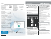
MAINTENANCE & INSPECTION
CAUTION
- Make sure you do not damage tip of fluid nozzle or seat section.
- Never use spare parts that are not Air Gunsa originals.
1. Pour remaining paint into another container. Clean fluid passages and
air cap set.Spray a small amount of cleaner to clean fluid passages.
- INCOMPLETE CLEANING CAN CAUSE PATTERN SHAPE DEFECTS.
ESPECIALLY CLEAN FULLY AND PROMPTLY AFTER USE WITH TWO-
COMPONENT PAINT.
2. Clean each section with brush soaked with cleaner and wipe out with
waste cloth.
- NEVER IMMERSE THE SPRAY GUN COMPLETELY IN SOLVENT, AS IT
CAN DAMAGE PARTS.
3. Before disassembly, clean fluid passages.
a. Disassemble fluid nozzle, while keeping fluid needle pulled (trigger-
ing) in order to protect its seat section.
b. Disassemble fluid needle set.
(only when strictly necessary)
c. Remove the fluid adj. knob and needle spring, extracting the spring
and fluid needle set, from the back of fluid adj. guide set still assem-
bled on the gun body.
Leakage from fluid nozzle set and fluid needle set seat sections.
Replace fluid nozzle set and fluid needle set, if leakage does not stop
after cleaning them.
If you replace fluid nozzle or fluid needle only, match
them carefully and make sure there is no further leakage.
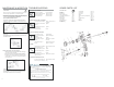
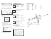
SPARE PARTS LIST
DESCRIPTION
Air cap Ref. 1
Fluid Nozzle Ref. 2
Nozzle holder Ref. 3
Pattern adjustment set Ref. 5
Fluid needle adjustment knob Ref. 6
Needle guide Ref. 7
Needle spring Ref. 8
Fluid needle Ref. 9
Needle packing nut Ref. 10
Air valve set Ref. 11
Air valve spring Ref. 11-1
Air valve shaft Ref. 11-2
Air valve seat Ref. 11-3
Trigger stud Ref. 12
Trigger Ref. 13
Air flow control valve (AZ3HTE2 AV) Ref. 14-1
Plug Ref. 14-2
Threaded bushing Ref. 15
Screw Ref. 16-1
Plug Ref. 16-2
Air nipple Ref. 17
GB