
Installation guide


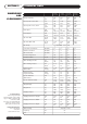

TECHNICAL DATA SECTION 2
5
A. Height of Heater mm 1623 1623 1623 1851
In 64 64 64 73
B. Diameter mm 720 720 720 720
In 28 28 28 28
C. Gas Connection mm 355 355 355 355
In 14 14 14 14
D. Cold Inlet mm 530 530 530 530
In 21 21 21 21
E. Optional Front Outlet mm 1307 1307 1535 1535
In 51 51 60 60
F. Height to Centre of Flue mm 2060 2060 1980 2217
In 81 81 78 87
G. Height to Flue Spigot mm 1780 1780 1780 2020
In 70 70 70 80
H. Min. Flue Horizontal mm 1100 1100 1260 1260
In 43 43 50 50
Max. Flue Horizontal mm 7000 7000 7000 7000
In 276 276 276 276
I. Min. Flue Vertical mm 1310 1310 1610 1610
In 51 51 63 63
Max. Flue Vertical mm 7000 7000 7000 7000
In 276 276 276 276
J. Electrical Connection mm 1250 1250 1250 1480
In 49 49 49 58
K. Flue Diameter mm 100/150 100/150 130/200 130/200
L. Flue Adaptor mm 95 95
In 4 4
ANDREWS MODEL NO. CSC39 CSC59 CSC78 CSC93
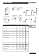
DIMENSIONS
AND
CLEARANCES
Not supplied with
these models
Horizontal or
Vertical Flue
1168mm
Minimum
Service
clearance
with
standard
Anodes.
500mm Recommended
for panel access and
switching. Absolute
min 300mm.
500mm Recommended for
panel access and switching.
Absolute min 300mm.
615mm
Minimum
Service
clearance
with Correx
Anodes.
Adaptor
Cold Water
Inlet 1
“
B.S.P.
Drain or Return
3/4” B.S.P.
Ideal Service clearance Dimensions
1125
Horizontal
Flue can
be rotated
360º
Tee & T/P Valve
supplied
Vent from here
if used for Top
Hot Water outlet
‘X’
H
H
K
I
I
Can be
used for
Hot Water
outlet or
can be
capped
Alternative
Hot Water
outlet
If side connection is
used for Hot Water
outlet Air vent must
be fitted at ‘X’
UNVENTED SYSTEM VENTED SYSTEM CSC78 and CSC93 Alternative Flue Systems
CSC39 and CSC59 Alternative Flue Systems
275.0
90.0
725.0 Min.
475.0
300mm
Minimum
N.B. Access of 500mm must be provided
one side for 6 months fan lubrication