Installation, Operation and Maintenance Bulletin OM76 Revision E Type ES76( ) 7.6-Meter ESA 7.6-Meter Earth Station Antenna Andrew Corporation 10500 West 153rd Street Orland Park, IL U.S.A. 60462 Telephone: 708-349-3300 FAX (U.S.A.): 1-800-349-5444 Internet: http://www.andrew.com Customer Service, 24 hours: U.S.A. • Canada • Mexico: 1-800-255-1479 U.K.
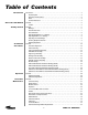
Table of Contents Introduction Introduction. . . . . . . . . . . . . . . . . . . . . . . . . . . . . . . . . . . . . . . . . . . . . . . . . . . . . . . . . . . . . . . . . . . . . . . . 3 Proprietary Data . . . . . . . . . . . . . . . . . . . . . . . . . . . . . . . . . . . . . . . . . . . . . . . . . . . . . . . . . . . . . . . . 4 Information and Assistance. . . . . . . . . . . . . . . . . . . . . . . . . . . . . . . . . . . . . . . . . . . . . . . . . . . . . . . . 4 Notice . . . . . . . . . . . . . .
7.6-Meter Earth Station Antenna Introduction Like all Andrew earth station antennas, the 7.6-Meter Earth Station Antenna provides high gain and exceptional pattern characteristics. The electrical performance and exceptional versatility provides the ability to configure the antenna with your choice of linearlyor circularly-polarized 2-port or 4-port combining network. That versatility is provided at the time of initial purchase, as well as in the future, as your satellite communication requirements evolve.
Proprietary Data The technical data contained herein is proprietary to Andrew Corporation. It is intended for use in operation and maintenance of Andrew supplied equipment. This data shall not be disclosed or duplicated in whole or in part without express written consent of Andrew Corporation. Information and Assistance Andrew Corporation provides a world-wide technical support network. Refer to the technical assistance portion of this this manual for the contact numbers appropriate to your location.
How to Use This Manual Overview The scope of this manual is intended to provide station personnel with the base installation, operation, and maintenance requirements necessary for a 7.6-Meter C-, X- or KuBand Earth Station Antenna. This manual provides a convenient reference for authorized operator/service personnel requiring technical information on general system or specific subsystem equipment.
Getting Started Overview The installation, operation, and maintenance of the 7.6-Meter Earth Station Antenna requires qualified and experienced personnel. Andrew installation, operation, and maintenance instructions are illustrated for such personnel. Additionally, the antenna should be inspected by qualified personnel to verify proper installation, maintenance, and condition of equipment as described in Preventive Maintenance.
NOTE: Failure to follow an installation procedure could result in damage to equipment or personal injury. Additional warnings will be displayed throughout this manual for your awareness. These warnings can be identified in warning boxes as shown in the following sample. Andrew disclaims any liability or responsibility for the results of improper or unsafe installation, operation, or maintenance practices.
Parts Verification Upon receipt of your order, the shipment should be verified to ensure that all parts have reached your site. This process should occur before the installation process begins. Andrew Corporation thoroughly inspects and carefully packs all equipment before shipment. If you find that there are missing components, please refer to page 9 for step-bystep instructions on how to properly report the equipment loss.
Returning Equipment Andrew Corporation tries to ensure that all items arrive safe and in working order. Occasionally, despite these efforts, equipment is received which is not in working condition.
Installation Procedures Overview This section provides installation procedures for the 7.6-Meter Andrew Earth Station Antenna. The installation procedures include instructions on the following antenna components: • Mount • Reflector-to-Mount Assembly • Reflector • Enclosure Foundation Preparation • Subreflector • Feed System (C-, X- and Ku-band) Before beginning the installation process on the ground mount assembly, ensure that the foundation has been prepared.
A-325 Tensioning During the installation process, there are several references to the A-325 hardware tensioning procedure. The A-325 hardware must be properly tensioned to avoid slippage between bolted surfaces under high loads. Slippage can cause the corresponding assembly to move, causing antenna misalignment. When designated, the A-325 hardware should be tightened according to the following tensioning procedure. NOTE: Tensioned bolts are for final connections only and should not be loosened for reuse.
Tripod Ground Mount Assembly The three-point mount is an elevation-over-azimuth mount optimized for geostationary satellite applications. The mount enables continuous elevation adjustment from 0 to 90°. Azimuth adjustment is ±90° and divided into three 120° ranges with 30° overlap. Follow the subsequent procedures for proper installation of tripod ground mount assembly. Azimuth Beam Assembly Step 1 All ground mount hardware is type A-325. Lubricate all A325 bolt threads with supplied stick wax.
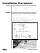
Support Legs Assembly Step 1 Attach 201327A joint assembly to 201313A beam assembly as shown in Figure 5. Attach 200083 angles to 201313A beam assembly as shown in Figure 5. • Use 7/8 x 2-1/4 in (57 mm) bolts and nuts for each connection Figure 5 Step 2 Attach 200088A joint assembly to 201313A beam assembly as shown in Figure 6.
Step 3 Raise 201313A beam assembly to upright position and attach 201315 supports to 201327A joint assembly as shown in Figure 7. • Use 7/8 x 2-1/4 in. (57 mm) bolts and nuts. • Insert bolts from 201327A joint assembly to supports. • Supports should be installed back-to-back with the flat of angle facing upwards. • Tighten supports until assembly can support itself. Figure 7 Step 4 Attach 201301/201302 rear pad assembly to 201315 supports as shown in Figure 8. • Use 7/8 x 2-1/4 in.
Step 5 Attach 201314 supports to 201301/201302 rear pad assemblies and 200884 joint assembly as shown in Figure 9. • Use 7/8 x 2-1/4 in. (57 mm) bolts and nuts • Insert bolt from inside of joint assembly to outside of support • Supports should be installed back-to-back with the edges forward and the flats of angles facing rear Figure 9 Step 6 Attach 201317 supports between angle pairs as shown in Figure 10.
Panning Frame Assembly Step 1 Attach 201487 panning frame to 221384 azimuth pivot assembly as shown in Figures 11 and 12. • Use 7/8 x 2-1/4 in.
Step 2 Attach 221608 joint assemblies to panning frame as shown in Figures 13 and 14.
Step 3 Attach 201316 support pairs to 221608 joint assemblies as shown in Figure 15. • Place supports back-to-back with edges out and flat of angle inward • Install 45967 spacer at midpoints of support pairs • Use 7/8 x 2-1/4 in (57 mm) hardware for each connection Figure 15 Step 4 Attach 221345 azimuth pivot assembly to 201316 support pairs. Attach 201596 mounting plates to 201458 azimuth pivot assembly tab as shown in Figure 16.
Step 5 Attach 201770 plate connecting 201484/201484-2 extension assembly to 201487 panning frame as pictured in Figure 17. • Use 7/8 x 2-1/4 in (57 mm) hardware • Insert bolts from inside panning frame assembly Figure 17 Step 6 Attach 201488 outrigger plate to opposite end of 201487 panning assembly. Attach 201481/201482 supports to outrigger plate as shown in Figure 18.
Step 7 Attach second 201488 outrigger plate to 201487 panning frame assembly as shown in Figure 19. • Use 7/8 x 2-1/4 in (57 mm) hardware • Insert bolts from inside assembly to outrigger plate Figure 19 Step 8 Attach 221721 elevation axis assembly to 201487 panning frame assembly and 221608 joint assemblies as shown in Figures 20 and 21.
Figure 21 Step 9 Attach 301741/301742 tripod joint bracket to 221721 elevation axis assembly as shown in Figure 22.
Step 10 Attach 300026 tripod channel legs to 301741/301742 tripod joint bracket as shown in Figure 23. • Use 7/8 x 2-1/4 in (57 mm) bolt, flatwasher and nut • Insert bolts from channel leg to joint bracket Figure 23 Step 11 Attach 301725 tripod tube weldment to 300026 tripod channel legs as shown in Figure 24.
Elevation Jackscrew Assembly Step 1 Attach 301771/301736 elevation jackscrew assembly to 201596 mounting plates as shown in Figure 25. Tighten connection. • Use 7/8 x 2-1/2 bolts and nuts Figure 25 Step 2 Loosen rubber boot from end of jackscrew. Turn elevation drive screw to extend jack to dimension 67.7 in (1719 mm) as shown in Figure 26. Apply grease to screw shaft. Reattach rubber boot.
Step 3 Prop 301771/301736 elevation jackscrew up to align with 301725 tripod tube weldment as shown in Figure 27. Figure 27 Step 4 Attach 301771/301736 elevation jackscrew to 301725 tripod tube weldment as shown in Figure 28. • Use 7/8 x 5-1/4 (133 mm) bolt. Fasten with heavy hex nut and flatwasher according to A-325 procedure with the exception of tightening the nut 1/2 turn from snug condition. Tighten jam nut in accordance with A-325 procedure. Apply supplied Loctite to threads to act as locking nut.
Azimuth Jackscrew Assembly Step 1 Insert 221923/223180 azimuth jackscrew tube into 221738 azimuth pivot assembly as shown in Figure 29. Insert jack carefully to prevent scratching jackscrew tube. Note: Ensure jackscrew assembly remains fully retracted at this time. 221738 221923/223180 Figure 29 Step 2 Apply RTV to flange surface as shown in Figure 29. Fasten jack to pivot using 7/8 x 23/4 in (70 mm) bolts and nuts. Mounting hardware is included with corresponding jack assembly hardware kit.
Step 3 Attach rear pad assemblies to rear foundation pads as pictured in Figure 31. 201327A JOINT ASSEMBLY 201313A BEAM ASSEMBLY 221345 PIVOT ASSEMBLY Figure 31 Step 4 Connect beam assembly using 7/8 x 2-1/4 in (57 mm) hardware. Tighten supports to beam assembly per A-325 tensioning procedure.
Step 5 Hoist elevation jackscrew assembly to mount. Attach 221384 azimuth pivot assembly to 221608 joint assembly with 7/8 x 2-1/4 hardware from pivot assembly to joint assembly as shown in Figure 32. Figure 32 Step 6 Attach 221435 azimuth pivot assembly to 201408 beam assembly with a line of RTV around the plate and four 7/8 x 2-1/4 in (57 mm) holts inserted from pivot assembly to beam assembly as shown in Figure 33.
Note: If optional motor drive system is included, install motors at this point. Refer to installation instructions provided with motor kits. Step 7 Refer to Figure 34. Position hoisting ropes on azimuth motor jack assembly so jack will not roll when hoisted. Attach one rope to motor frame next to gearbox to balance assembly. Tie up loose conduit before lifting jack. Figure 34 Step 8 Refer to Figure 34. Position hoisting ropes on motor/jack assembly so jack will not roll when hoisted.
Step 10 Extend jackscrew to meet outrigger assembly. Loosely re-attach outrigger plate to pin assembly in azimuth jackscrew as shown in Figure 35. Note: Realignment of panning frame/pivot assembly may be necessary to ensure proper alignment of azimuth jackscrew pin. Snug panning frame/pivot assembly hardware and fully extend azimuth jackscrew to ensure binding does not occur throughout entire azimuth pivot range.
Installation Procedures
Installation Procedures
Installation Procedures
Installation Procedures
Installation Procedures
Installation Procedures
Installation Procedures
Installation Procedures
Installation Procedures
Installation Procedures
Installation Procedures
Installation Procedures
Installation Procedures
Installation Procedures
Installation Procedures
Installation Procedures
Installation Procedures
Installation Procedures
Installation Procedures
Installation Procedures
Installation Procedures
Installation Procedures
Installation Procedures
Installation Procedures
Operation Overview After you have completed the assembly of your antenna, you are now ready to become operational. In order to operate the earth station antenna, you will need to direct it to the desired satellite adjusting both the elevation and azimuth angles appropriately. The following procedures provide details on how to correctly position your antenna on the desired satellite. Acquiring A Satellite There are several procedures that may be used to properly acquire the satellite.
The following steps provide the procedure for acquiring a satellite. Step 1 Manually move the antenna in the azimuth (scanning back-and-forth) to achieve the maximum (greatest amplitude) transponder signals. • Scan in one direction until the amplitude continues to diminish and then scan in the opposite direction until the same condition occurs. • Return to the position yielding the greatest amplitude. The maximum azimuth excursion from the original setting should not exceed plus or minus 1.
Step 5 If the signal amplitude diminishes and does not increase (position B) to the level noted when the antenna was peaked on the side lobe, the antenna is moving away from the main beam; reverse the direction of the antenna movement. From the original side lobe position (position A), the signal amplitude should now diminish to a null point at position C (minimum amplitude showing only signal noise) and then symmetrically increase again to the same level at position D as noted at position A.
Step 9 With all 24 transponder signals of approximately equal amplitude appearing on the spectrum analyzer screen determine the specific antenna system and satellite parameters. Rotate the feed assembly as required until the appropriate (odd or even) transponder signals are maximized.
Subreflector Adjustment After the satellite has been acquired and testing has taken place with the spectrum analyzer, the subreflector may need to be adjusted to maximize optimum performance of your antenna. The following procedures should be followed if a subreflector adjustment is required to maximize optimum performance. NOTE: All INTELSAT Type Approved antennas do not require subreflector adjustment.
Preventive Maintenance Overview This section contains periodic preventive maintenance instructions for the 5.6-Meter Earth Station Antenna. Included in this section are inspection and preventive maintenance procedures including cleaning and lubrication, painting, and an operational voltage/current checkout procedure deemed within the capabilities of the average station technician.
Mechanical Parts Inspection Local Control/Motor Drive Controller scraper, stiff brush (bristle or wire in the case of rust or other corrosion), or cloth or compressed air at 25 to 40 psi. Any accumulated imbedded dirt, corrosion, grease, or oil deposits that require further cleaning may be removed with a bristle or wire brush and a cleaning solvent such as trichlorethylene or equal. After cleaning, allow cleaned parts to dry for 10 to 15 minutes before placing the equipment into operation.
pungent odor indicative of burning vanish denoting overheating or a total breakdown. • Check all terminal boards for broken or missing terminals and stripped threads. Check tightness of lead attaching hardware. • Check each starter for a make-after-break provision through the release of one pushbutton as the alternate pushbutton is pressed. • Check the relays and contactors for free operation of the armatures and contact condition.
and minus direction from the local control/motor drive controller at least once every three months during antenna down time. Check the mechanical limit switches provided at the end points stop antenna and feed movement, and limit travel to prevent structural interference and damage. Check the mechanical limit switches for corrosion and water entry and the arm on each feed limit switch for free movement without binding.
tain all electrical grounding connections (including cross-axis grounding straps) are intact and secure, not corroded or broken. Thoroughly clean any noticeable corroded portions of grounding cables, unplated portion of universal terminals and corresponding mounting surfaces using a wire brush. Replace rather than tighten any loose A-325 structural hardware. The hardware distorts at initial installation and once loosened will not maintain the required high strength friction connection.
Step 4 Step 5 Turn the AZIMUTH EAST/WEST switch to either position and while the antenna is rotating, carefully use a clamp on ammeter in accordance with the ammeter manufacturer’s instructions to take current readings off each of the three conductors (phases) connected to the load side of the azimuth drive motor circuit breaker. Record the current draw in the equipment log and compare the readings to the reference values entered in the installation/acceptance check off.
Preservation of Component Parts Aluminum Parts Remove all loose paint and corrosion by scraping, wire brushing, or using steel wool. If using steel wool near the feed window, make sure that none remains on the feed horn window. Edges of existing paint can be blended with the metal surface by using a fine grit sandpaper. Wipe the surface to be painted with a soft rag dampened in trichlorethylene, lacquer thinner or equal.
tube assembly and corresponding thrust pads. Securely replace access plugs in square tube weldment. Be certain to remove any protective caps and clean off each lubrication fitting prior to injecting fresh grease. The elevation and azimuth jackscrew assemblies are equipped with a grease fitting and corresponding pipe plug on opposite sides of the jack housing. Remove the appropriate pipe plug and fill with with grease until lubricant seeps from the pipe plug opening. Replace and securely tighten pipe plug.
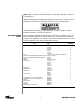
Lubrication Chart Lube Components Point to be No. Lubricated 1 Frequency (Months) 3 6 Type of Service Type of Lube No. of Lube Points or Quantity Pressure Fitting SHC32 1 Pipe Plugs SHC624 10 Oz C** Pipe Plugs SHC624 34 Oz. 12 1. Elevation Jackscrew Housing 2.1 Elevation Jackscrew Gear Housing Fill and Drain 3.2 Elevation Drive Intermediate Gearbox Fill and Drain 4. Elevation Jackscrew Pivot Pin, upper X Pressure Fitting SHC32 1 5.
Pressure Fitting 5 9 10 Pressure Fitting Worm Gear Polarization Pillow Drive Gear Blocks (2) Gearbox Fill Pressure Fitting 6 7 8 4 Heater Control Gearbox Fill Gearbox Fill Gearbox Level 1 2 3 Pressure Fitting Gearbox Drain Gearbox Level Gearbox Fill Local Motor Control Note Medium-speed motors shown for illustrative purposes only.
Pressure Fitting 5 9 10 Pressure Fitting Worm Gear Polarization Pillow Drive Gear Blocks (2) Pressure Fitting 6 7 8 4 Heater Control Gearbox Drain 1 2 3 Pressure Fitting Gearbox Drain Gearbox Level Local Motor Control Gearbox Level Medium-Speed Antenna Lubrication Points 69 Preventive Maintenance