
Technical data
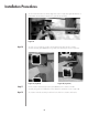
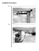

Remove the two indicated strut-support setscrews, and attach the base angle to the
corresponding strut support using the supplied 1/2 inch clamping nuts and the previously
removed strut-support setscrews as shown in Figure 34.
WARNING: Azimuth brakes have been factory set. Do not readjust brakes to facilitate the use
of actuators.
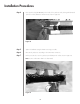
Securely tighten the remaining mounting hardware to achieve the clamping force.
Follow directions for “Acquiring a Satellite”.
Repeat the entire procedure for the remaining strut assembly.
After the adjustments have been made, the manual actuator should be removed. The
following steps provide the procedure for the proper removal of the manual actuator
assembly.
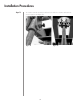
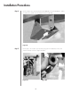
Remove the manual actuator assembly by first removing the hardware securing the actuator to
the base angle.
NOTE: The adjustment kit assembly should be removed after the antenna has been adjusted.
Store the manual actuator assembly and the corresponding hardware in a dry area for future
use.
Remove the remaining clamp segments with the corresponding hardware.
After the antenna is pointed at the satellite, tighten all azimuth and elevation set screws to 35
foot-pounds.
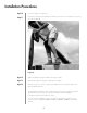
If you are assembling a motorizable pedestal mount (P/N 208800) follow the directions
for ground mount assembly before beginning this section. The following steps provide the
procedure for assembling the motorizable pedestal ground mount.
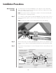
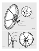
Bolt the azimuth pivot assembly (top and bottom) brackets to the ground mount assembly using
5/8 inch hardware (hex bolt, flatwasher and hex nut) as shown in Figure 35.
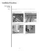
Installation Procedures
Step 4
Step 5
Step
6
Step 7
Manual Acturator
Assembly Removal
Step 1
Step 2
Step3
Motorizable
Pedestal Ground
Mount Assembly
Step 1
33
Figure 35