
Technical data
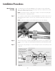
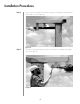
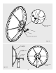

The manual actuator assembly (P/N 207882) is used to adjust the elevation and azimuth
angles of the 4.0-meter antenna. The following steps provide the procedureused to assemble
and install the manual actuator assembly.
NOTE: This assembly should be conducted upon completion of the antenna assembly (after
feed assembly). Refer to “Acquiring A Satellite”.
Loosely attach the manual actuator assembly (P/N 207882) to the elevation strut as shown in
Figure 33 using clamp segments, 1/4 inch screw, lockwasher and hex nut in each of the 12
connections.
NOTE: The drain hole should be positioned downward for proper water drainage.
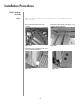
Installation Procedures
Manual Actuator
Assembly
Step 1
Step 2
Step 3
32
Figure 33
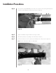
Figure 34
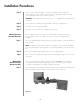
Attach the base angle to the actuator (P/N 202661) using 1/2 inch screws, flatwashers and
hex nuts as shown in Figure 34. AVOID EXCESSIVE TORQUE ON THE MOUNTING HARD-
WARE.
Ensure that the locking strut-support set screw is firmly tightened on the strut assembly as shown
in Figure 34.
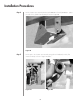
If interference occurs with
set screw and actuator
bolt, remove set screw. After
antenna adjustment and
removal of actuator
assembly, replacd the set
screw.
Optional Welded
Bracket Mount
21.64 Retracted
39.20 Extended
Strut Support
.25 Hex Head Screw
Lock Washer
Flat Washer
Hex Nut
Clamp Segment
Az/El Strut
Manual Actuator
.25 Lock Washer
Flat Washer
Hex Head Screw
Hex Nut
.75 Across Flats
(Customer To
Supply Wrench)
.50 Hex Head Screw
Lock Washer
Flat Washer
Hex Nut
.50 Locking Strut
Support Set Screw
.50 Hex Nut
.50 Strut
Support
Set Screw
Drain
Hole
Figure 34