
Technical data
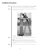
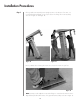
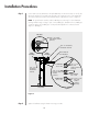
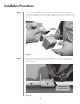

Position and mount the azimuth tiller arm (P/N 203112) to the tiller-arm bracket on the left side
(facing the satellite) of the ground mount assembly. This mounting position of the azimuth tiller
arm is dependent upon pre-determined azimuth range requirements as shown in Figure 21.
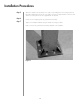
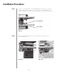
NOTE: The ground mount assembly enables 180 degrees positioning for selected azimuth
viewing. Azimuth range coverage is plus or minus 90 degrees, divided into three 120 degree
continuous ranges with a 30 degrees overlap. Elevation adjustment is continuous from 0
degrees to 90 degrees.
Tighten the hardware using the A-325 tensioning procedure.
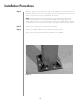
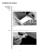
Installation Procedures
Step 3
Step 4
26
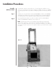
Figure 21
3/4” x 1-1/2” Bolt,
Lock Washer and Nut
(6 Places)
Angle
Assembly
3/4” x 2”
A-325 Bolt,
Flat Washer
and Nut
3/4” x 2” A-325 Bolt,
Flat Washer and Nut
203112 Azimuth
Strut Weldment
Front View
Side View
Left Position
-90˚ to +30˚
3/4” x 1-1/2”
Bolt, Lock Washer
and Nut
(6 Places)
3/4” x 1-1/2”
Bolt, Lock
Washer and Nut
(6 Places)
Center Position
-60˚ to +60˚
Right Position
-30˚ to +90˚
Angle
Assembly
3/4” x 1-1/2”
Bolt, Lock
Washer
and Nut
(6 Places)
Top View