
Technical data

During the installation process there are several references to the A-325 hardware tensioning
procedure. The A-325 hardware must be properly tensioned to avoid slippage between
bolted surfaces under high loads. Slippage can cause the corresponding assembly to move,
causing antenna misalignment. When designated, the A-325 hardware should be tightened
according to the following tensioning procedure.
Note: Tensioned bolts are for final connections only and should not be loosened for reuse.
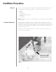
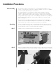
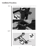
Lubricate the bolt threads with the provided stick wax to reduce friction.
Insert the bolt, and add a flat washer - if required. Do not allow wax under the flat washer.
Add the nut and finger-tighten.
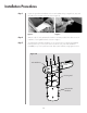
After the connections are complete, tighten the bolts until the surfaces are joined and the nuts
are snug (for example, full effort of a person using an ordinary spud wrench).
Do not proceed with Steps 5 and 6 unless the connection is final and is not intended to be
loosened again.
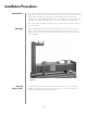
Note: If the bolts are loosened after Steps 5 and 6, discard and replace with new hardware.
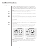
Using a felt-tip marker, mark the nuts and the ends of the bolts with a straight line as shown in
Figure 2a and 2b.
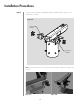
Tighten the nuts further with an extra-long wrench until the nuts are moved 1/3 turn (120
degrees) as shown in Figure a for bolt lengths shorter than four diameters and 1/2 turn
(180 degrees) as shown in Figure 2-B for bolt lengths longer than four diameters.
Note: Do not perform A-325 tensioning procedure during assembly process unless
specifically designated by installation instructions. Final tightening will occur after mount
is fully assembled.
Installation Procedures
A-325 Tensioning
Step 1
Step 2
Step 3
Step 4
Step 5
Step 6
13
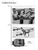
Use Felt Marker
Use Felt Marker
Before
Tensioning
After
Tensioning
Before
Tensioning
After
Tensioning
For Bolts Shorter Than 4 Diameters For Bolts Longer Than 4 Diameters
Figure 2a. A-325 Tensioning Figure 2b. A-325 Tensioning