Users Guide OMACS3000 – Rev E ACS3000 Antenna Control System Antenna Control System with SmarTrack® April 11, 2006 Andrew Corporation 10500 West 153rd Street Orland Park, IL U.S.A. 60462 Printed in U.S.A. Telephone: 708-349-3300 FAX (U.S.A.): 1-800-349-5444 Internet: http://www.andrew.com April 11, 2006 Customer Service, 24 hours: U.S.A. • Canada • Mexico: 1-800-255-1479 U.K.
11-APR-06 Rev E OMACS3000 List of Figures................................................................................................................................. 4 System Description ........................................................................................................................ 5 Overview ................................................................................................................................. 5 Summary..............................................
11-APR-06 Rev E OMACS3000 Tracking Summary ................................................................................................................ 35 Satellite Table Screens.......................................................................................................... 36 Satellite Table Screen ........................................................................................................... 37 Working Satellite Table Screen ....................................................
11-APR-06 Rev E OMACS3000 List of Figures Figure 1: System Diagram .............................................................................................................. 6 Figure 2: LMKVS-CPU Admin Application .................................................................................... 12 Figure 3: Home Screen - System Is Not Initialized........................................................................ 13 Figure 4: Home Screen - System Is Initialized ................................
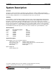
11-APR-06 Rev E OMACS3000 System Description Overview The purpose of this User Guide is to describe the steps required to configure, initialize, and operate the ACS3000 Antenna Control System with SmarTrack®. All parameters are fully programmable and displayed from a PC running a Web Browser or an existing station monitor and control system. Summary The ACS3000 is a complete kit that provides precision three-axis control of all the Andrew earth antennas from 2.4 to 9.45 meters in size.
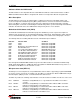
11-APR-06 Rev E OMACS3000 LMKVS-CPU Motors Optional DC (Optional) Fiber converter Fiber converter Ether net hub PC with browser Motor Control Unit (MC-2) RS-232 SABus protocol Ethernet 10BaseT RS-232 Multi-protocol Accessory power Beacon Interface Box Beacon Receiver Local control or 0 – 10V sig strength Resolvers Single Board Computer (Linux Board) UTP Ethernet 10BaseT Limit Switches HH Protocol Rack Mounted ADU Handheld Unit Figure 1: System Diagram The LMKVS-CPU is the overall man
11-APR-06 Rev E OMACS3000 Indicators Within the LMKVS-CPU The MC-2 and the Low Temperature Board contain LED's that indicate certain fault and status conditions. Within the LMKVS-CPU the MC-2 is designated A1 and the Low Temperature Board is designated A5. MC-2 Description The MC-2 Motor Control Logic Assembly handles feedback from antenna mounted limit switches and resolvers and provides Variable Frequency Drive (VFD) and motor control for the antenna mounted drive motors.
11-APR-06 DS-5 DS-6 DS-7 Rev E OMACS3000 STOP Illuminates steady YELLOW when the Emergency Stop Switch is depressed. MICRO RESET Illuminates steady RED when MPU-17 microprocessor is in a reset condition. Blinks RED in a continuous reset condition or buss failure.
11-APR-06 Rev E OMACS3000 Antenna Display Unit (Optional) The Antenna Display Unit is a rack mountable (two rack height) antenna control unit (ADU) that is designed to provide direct interface to a local area network to provide a remote control graphical user interface (GUI) for the ACS3000 Antenna Control System.
11-APR-06 Rev E OMACS3000 Dimensions: 19" W x 1.75" H x 4" D Weight: 3 lbs Approvals: EN 60950 (CE), EN 61326 Class A UL 60950, FCC Part 15 Class A Power: 85-250 VAC, 0.
-APR-06 Rev E OMACS3000 System Setup Operator’s Computer Setup The ACS3000 is controlled from an operator's computer through an Ethernet connection to the LMKVS-CPU. The LMKVS-CPU may be connected to the operator's computer via a LAN (Local Area Network) or via a direct connection using an Ethernet crossover cable. A browser such as Internet Explorer or Netscape is necessary to activate the Java applet that manages the ACS3000 LMKVS-CPU.
11-APR-06 Rev E OMACS3000 Figure 2: LMKVS-CPU Admin Application Follow the menu options to set up the antenna controller box IP address. In order for the changes to be applied, the 'Save New Values to Config File' option must be executed and the antenna controller box must be rebooted (option R). The reboot of the antenna controller box will cause the telnet session to be dropped. The exit option does not have to be executed in that case.
11-APR-06 Rev E OMACS3000 System Screens ACS3000 Screens Now that the operator's computer is correctly setup, and the LMKVS-CPU antenna controller has a valid IP, the operator can control the antenna via the ACS3000 GUI interface and the Java applet screens. The operator may bring up the Internet browser and enter the antenna controller IP address (for example, the default IP of 192.168.1.76) in the browser address line. The first screen to come up is the Home Screen.
11-APR-06 Rev E OMACS3000 On the left hand of the screen, above the control panel, is the status panel. The status panel contains four lines of information, three of which are always displayed. The first line announces whether a SmarTrack® model is available or not (No Model or Model Ready). The second line reports the tracking mode (Standby, Step Track, SmarTrack®, NORAD Track, or INTELSAT Track). The third line displays alarm when alarms are present.
11-APR-06 Rev E OMACS3000 Figure 5: Home Screen - Hand Held Controller Connected Set Time/IP If the system comes up in the System Not Initialized state, the system must be initialized before the antenna may be moved. In fact, the antenna control program will not allow the operator to enter any screen that can control antenna movement. The only screens available are Logs/Alarms, Initialization, and Set Time/IP.
11-APR-06 Rev E OMACS3000 Figure 6: Set Time Screen Initialization Screens The antenna system controller must be initialized in order for the operator to gain full control of the antenna. Initialization calibrates the resolvers so that the angles read from the Motor Control Unit have a valid reference to the antenna position. Initialization also sets up the site location, which is necessary in order to determine the satellites visible to the antenna.
11-APR-06 Rev E OMACS3000 Figure 7: Initialization Entry Screen Test Only Password Protection Screen The Test Only button brings up Figure 8, the Test Only Password protection screen. The operator must enter the correct password in order to bring up the factory test screen. This screen is for factory test only.
11-APR-06 Rev E OMACS3000 Figure 8: Test Only Password Screen Pre-Initialization Antenna Setup The ACS3000 defines movement in the Az axis as either East or West. In the Northern Hemisphere, because the antenna points in a southerly direction, East is defined as moving with a decreasing resolver reading and West as an increasing resolver reading (see Figure A). In the Southern Hemisphere, West is defined as a decreasing resolver reading and East as an increasing resolver reading (see Figure B).
11-APR-06 Rev E OMACS3000 Figure 9: Pre-Initialization Antenna Setup Initialize Site Location Selecting the Start Initialization button from the Initialization Entry Screen will cause a popup warning window to be displayed as shown in Figure 10. This warning is a reminder that the antenna installation hardware limits must be validated with a hand held unit prior to initializing with the wizard.
11-APR-06 Rev E OMACS3000 The pol motor type is selected from a pull down menu. The valid pol motor types are: no pol motor installed, single speed (1:1 ratio) pol motor, and dual speed (2:1 ratio) pol motor. Refer to Table 1 to determine the appropriate pol motor ratio. Figure 11: Initialize Site Location Screen Antenna Size 3.6M, 4.5M 3.7M, 5.6M Ku 4.9M, 6.5M 7.3M, 7.6M, 8.1M, 9.3M, 9.
11-APR-06 Rev E OMACS3000 Figure 12: Visible Satellites Computed Screen Figure 13: Satellite Table Downloaded to PC Popup Window Verify Jog Direction Before starting this step in the initialization process, the operator MUST place an observer near the antenna who can be in constant communication with the antenna controller operator.
11-APR-06 Rev E OMACS3000 The operator must select the buttons to move in each of the directions allowed by the screen. If the pol drive is not installed, only East, West, Up and Down jog directions will be displayed. The observer must let the operator know if the direction commanded by the operator is the same that the antenna actually moves. If any direction movement is incorrect, initialization must stop and the antenna wiring must be corrected before restarting the initialization.
11-APR-06 Rev E OMACS3000 up or down. All four directions must be jogged to their limit and all four check boxes must be displayed before the operator can go on to the next step in the Initialization Wizard. Figure 15: Verify Hardware Limits Screen Verify Pol Hardware Limits The antenna observer used for the AZ and EL Hardware Limits verification is necessary for the Pol hardware limits verification as well.
11-APR-06 Rev E OMACS3000 Figure 16: Single Speed Pol Hardware Limits Screen Dual Speed Pol Drive Hardware Limits If a dual speed (2:1 ratio) pol drive is installed, the operator first moves to the counter-clockwise limit as directed by the screen. (See Figure 17) The operator will jog until that axis reaches the physical limit. The operator will know that the limit is reached when that direction checkbox is checked.
11-APR-06 Rev E OMACS3000 Figure 17: Dual Speed Pol Hardware Limits Screen Select Base Satellite This step in the initialization process selects the satellite that will be used to peak the beacon, compute the look angles, and calibrate the azimuth and elevation resolvers. The screen normally displays visible satellites in black font while satellites in red font are not visible from the current site location.
11-APR-06 Rev E OMACS3000 Figure 18: Select Base Satellite Screen Peak on Base Satellite Once the satellite base is chosen, the antenna controller operator must peak up on that satellite. If the beacon receiver is connected, the readings from the beacon level may be used to peak. Otherwise, the operator must use another source to identify when the antenna is peaked on the satellite, refer to the satellite acquisition procedure below.
11-APR-06 Rev E OMACS3000 The specific procedure to acquire the satellite is: 1. Connect the Spectrum Analyzer to the LNA output or convenient downlink monitor port. 2. Set the Spectrum Analyzer center frequency to the correct frequency for the satellite to be acquired. 3.
11-APR-06 Rev E OMACS3000 Figure 19: Peak on Base Satellite Screen Elevation Increments - 0.5° Start Point ± 2° in Azimuth - 2° + 2° Second Start Location Point + First Scan First Scan - 0.
11-APR-06 Rev E OMACS3000 Automated Set Software Limits This step in the Initialization Wizard is an automated step that gets activated as soon as the observer box is checked. The antenna controller operator is not required to enter anything for this step but may interrupt the process with an emergency stop. (See Figure 20.) WARNING An observer must be at the antenna to request an emergency stop if the hardware limits fail.
11-APR-06 Rev E OMACS3000 Direction Minimum Maxium Az East 5 deg 175 deg Az West 185 deg 355 deg El Down 0 deg 40 deg El Up 50 deg 90 deg Pol CCW 0 deg 89.9 deg Pol CW 90.1 deg 180.0 deg Table 2: Software Limits Ranges Once all of the software limits have been set and all of the check boxes have appeared, Figure 20 will be displayed and the operator must select OK (see Figure 21), then next, to continue with the next initialization step.
11-APR-06 Rev E OMACS3000 Figure 22: Enter Tracking Parameters Screen Review Parameters The review parameter screen (see Figure 23) is displayed either when the Initialization Wizard has been completed or when the antenna controller operator requests the review parameter screen directly from the initialization entry screen (see Figure 7). The operator may change any or all of the parameter values in the white boxes.
11-APR-06 Rev E OMACS3000 Figure 23: Review Parameters Screen Initialization Complete This screen (see Figure 24) comes up when all steps of the initialization wizard have been completed and the review parameters screen has been canceled. Note that each of the configuration status segments is checked and that the position/jog and tracking buttons are no longer grayed out. This screen is entered after the review parameters have been verified and saved by selecting the cancel button.
11-APR-06 Rev E OMACS3000 Figure 24: Initialization Complete Screen Normal Operational Screens The rest of the screens displayed and discussed in this section are available only after all the setup and initialization processes have been completed correctly. The following screens will be in use the majority of the time. Position/Jog This operational screen (see Figure 25) allows the operator to move the antenna to the desired position or jog in a desired direction.
11-APR-06 Rev E OMACS3000 error, axis timeout error, current overload fault, resolver fault, and VFD fault. If the cleared error is persistent, the next MCU status message will reset the fault. The Save Current Position as Peaked button allows the operator to save the current position in the satellite table as the peaked position of the base satellite. All three axes – az, el, and pol – are saved and will be used when the operator selects a satellite and moves to that satellite.
11-APR-06 Rev E OMACS3000 Figure 26 shows the base satellite as 26498 / GALAXY 4R. If the operator wishes to track a different satellite, he must select that satellite in the satellite table screen. The tracking mode parameters that are modifiable from this screen are the scan cycle time, the scan cycle level, the low signal level, the beacon offset value, and the downlink frequency.
11-APR-06 Rev E OMACS3000 message for low signal will be issued but does not suspend antenna movement if the model is valid. The Smart Track model will become invalid after two days with no new valid peaks. If NORAD track is selected the operator must ensure that the system time is correctly set to UTC time. The NORAD algorithm uses UTC to calculate the azimuth and elevation angles. The site location must also be accurate. Significant errors may result if time and location are not correct.
11-APR-06 Rev E OMACS3000 The Satellite Table screen has two tabs, which determine how the table is displayed. The Satellite Table tab displays the full satellite table while the Working Table tab displays only the satellites selected by the operator for the working table. Both screens allow the operator to order the displayed table by clicking on the column on which the table is to be sorted. For example, clicking on the Sat Num column will sort the table by satellite number in ascending order.
11-APR-06 Rev E OMACS3000 Figure 28: Satellite Table Screen Working Satellite Table Screen The Working Satellite Table Screen displays all the satellites that have been added to the working table. In addition to the NORAD ID, the name, the satellite longitude, and the visible flag, this screen displays the computed az, el look angles, peaked az, el, and pol angles (if any), and flags indicating when NORAD or INTELSAT data is available.
11-APR-06 Rev E OMACS3000 Figure 29: Working Satellite Table Screen Satellite Entry Edit If the operator chooses to edit a working table entry, the Satellite Table Edit Screen will pop up (see Figure 30). He can then modify any or all parameters in the satellite table entry as listed. These parameters may be typed in or copied and pasted from another screen. The cut and paste capabilities are dependent on using Ctrl-C and Ctrl-V edit controls rather than mouse controls.
11-APR-06 Rev E OMACS3000 Figure 30: Satellite Table Entry Edit Screen Logs/Alarms Events and alarms are tabulated in a circular file that contains the time of the event/alarm, the description of the event/alarm, and any pertinent data. Many of the events are informational and are being logged for diagnostic purposes. Alarm events are often included twice - once when the alarm condition occurs, and again when the alarm condition is corrected.
11-APR-06 Rev E OMACS3000 Figure 31: Log/Alarms Button Right Click Display Log Screen When the operator first selects the Logs/Alarms button, the system reads the complete event log and orders the events from the most current to the oldest. Once the full event log is read, any new events that occur will be inserted at the top of the list. The Logs list displays the events in black and the alarms in red.
11-APR-06 Rev E OMACS3000 Figure 32: Logs Screen Alarm Screen The Alarms screen is a subset of the Logs screen. Selecting the Alarms screen will clear the alarm status line in the Status Box if the alarm condition has ceased. With the Alarm acknowledged, the Status Box will continue to show the flashing Alarm if an alarm condition still exists. Alarm and Events Descriptions The following messages appear in the Alarm/Logs screen.
11-APR-06 Rev E OMACS3000 "Invalid satellite data entered for satID=nnnnn" Operator made error in editing or adding satellite data to satellite with the Norad ID of nnnnn. The operator must correct the satellite entry. "MCU error ON (or OFF) - Az East Hardware Limits". Az East Hardware Limits reached. "MCU error ON (or OFF) - Az West Hardware Limits". Az West Hardware Limits reached. "MCU error ON (or OFF) - El Up Hardware Limits". El Up Hardware Limits reached.
11-APR-06 Rev E OMACS3000 "MCU error ON (or OFF) - Pol Direction". Pol Direction. Axis is moving in the opposite direction of the commanded position. "MCU error ON (or OFF) - MCU error On (or Off) - Az Current overload". Az Current overload. "MCU error ON (or OFF) - El Current overload". El Current overload. "MCU error ON (or OFF) - Pol Current overload". Pol Current overload. "MCU error ON (or OFF) - Az Resolver fault". Az Resolver fault. "MCU error ON (or OFF) - El Resolver fault". El Resolver fault.
11-APR-06 Rev E OMACS3000 "Track mode = cccccccccc" New track mode selected. "Satellite table contains nnn visible satellites" Satellite table contains nnn visible satellites. "Working Satellite table contains nnn satellites" Working Satellite table contains nnn satellites. "Modified satellite ID=nnnnn" Modified satellite. "Added satellite ID=nnnnn to working table" Added satellite to working table. "Selected satellite ID=nnnnn" Selected satellite.
11-APR-06 Rev E OMACS3000 "Invalid MCU move: snd rsp" Invalid move request where the snd values are the requested az, el, and pol and the rsp values are the MCU az, el and pol. The MCU sends back a response of 999.999 in any axis where the requested value is out of range. " Invalid VFD type " Invalid VFD type . “TRACKD mode response: Track mode = cccccccc” Track daemon mode request response.
11-APR-06 Rev E OMACS3000 Figure 34: Celestrack Web Site 47 of 51 System Screens
11-APR-06 Rev E OMACS3000 Figure 35: NORAD Data Set Save the displayed output as a file in directory C:\ACS3000\antennaID and name the file geo.txt by selecting File -> Save As from the browser. Once the updated NORAD data file has been saved to the correct directory on the local computer, the operator may update the satellite table with the new data. Selecting the Update Table button on the control panel will merge the NORAD data with the current satellite data.
11-APR-06 Rev E OMACS3000 If the operator selects the Update Table button when no geo.txt file has been loaded into the local directory (C:\ACS3000\antennaID\) will generate a different popup window as display by Figure 37. This allows the operator to use the current geo.txt file that is already loaded on the ACU. This may be necessary to correct errors in Norad data on the table entered by editing.
11-APR-06 Rev E OMACS3000 Figure 38: Update Software Button Figure 39: Update Software Confirmation Figure 40: Update Software Request Denied 50 of 51 System Screens
11-APR-06 Rev E OMACS3000 If the operator accepts the update software confirmation, another popup window will notify the operator that the update has been completed and that the browser must be closed, as the ACU system will have to reboot for the update to complete. After the operator allows enough time for the system to reboot, he may bring up the browser again and verify that a new release of software has been loaded by checking the Set Time/IP window and identifying the software release loaded.