
User guide


Bulletin II-102051-EN • Revision B November-2007 3
A typical TMA system consists of TMAs, Bias Tees, and PDU with accessories. For its function, the
system also depends on the proper configuration of other antenna line equipment, including feeders
and jumpers, surge arrestors, antennas, etc.
This section provides single sector illustrations of several RF path configuration examples. While
frequency bands vary and variations can occur, the examples provide guidance for many common
situations.
Contact your Andrew Corporation Sales Representative for recommendations on applicable system
components.
!,"
*++./0
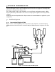
Figure 1 shows a dual-band TMA system using shared feeders. Diplexers (crossband couplers)
combine the bands at the BTS level. At the tower top, the TMA incorporates a diplexer at its BTS
port.
Figure 1: Conventional diplexed TMA system