
User guide

26 November-2007 Bulletin II-102051-EN • Revision B
'( )#
( !
Beginning with revision 02, the Multimode PDU supports special purpose modes M
ODE
A and M
ODE
B in addition to the LO
C
URRENT
and HI
C
URRENT
modes, which are supported by all revisions.
M
ODE
A and M
ODE
B are intended for use in specific site configurations not described herein. The
user will need additional information if using M
ODE
A and M
ODE
B in these intended configurations.
Included here is a full description of Mode A and Mode B operation as it applies to the Multimode
PDU.
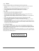
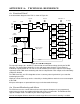
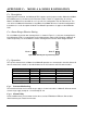
( " ''
To select M
ODE
A, position two shunting blocks as shown in Figure C-1. Only one shunting block is
included with the PDU. A second block can be obtained from another PDU operating in M
ODE
B, or
ordered separately. To select M
ODE
B, remove shunting blocks from the Alarm Range Selector.
LO CURRENT
HI CURRENT
LO CURRENT
HI CURRENT
Mode A Mode B
Figure C-1: Shunting block positioning
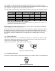
( 7
The specific characteristics of M
ODE
A and M
ODE
B operation are summarized in the table below. All
other characteristics remain as described above for the LO
C
URRENT
and HI
C
URRENT
modes.
/%*+ '(+ '(6 '(6
!(
#% 5.2 5.2 5.
% .2/?.4 .2/?.4 .4?2.
(% 6.B 6.B 622
$' 6A/ 6A/ 6A/
!9< 7 7 7
5,,+,+4
The normal and short circuit current ranges apply as shown in the table. In M
ODE
B, different normal
current ranges apply to outputs 1-3 and to outputs 4-6.
,:-
A fault condition must persist for 60 s before the associated TMA Alarm LED turns R
ED
and the
Alarm Interface goes into the A
LARM
state.