
User guide

22 November-2007 Bulletin II-102051-EN • Revision B
Andrew TMAs are equipped with internal fault monitoring and will raise or lower their current
consumption as a means to signal a fault condition to the PDU. Abnormal current consumption can
also result from other problems in the DC path from PDU to TMA.
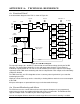
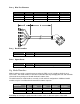
The table below summarizes the behavior of the PDU in the LO
C
URRENT
and HI
C
URRENT
modes:
/
%
3/%
'(*+
12%
'(*+
+*
34#
#%
/
+*
2$
!( &
#% 5. 5. &
% 2?./4 .4?2. =
&
(% 6.74 622 &
$' 6A 6A "
2
1
Applies when the TMA Alarm DIP switch is ENABLED.
2
If an alarm has previously occurred, the TMA Alarm LED will be latched RED until reset by the user.
3
SHORT CIRCUIT PROTECTION state (see below).
Beginning with revision 02, the PDU also supports special purpose modes M
ODE
A and M
ODE
B.
Refer to Appendix C for further information.
When in the S
HORT
C
IRCUIT
P
ROTECTION
state, the DC Output is turned off. At intervals of 200 ms,
the output is turned on in attempts to recover. If the short circuit condition persists, the output is
immediately turned off again. Output duty cycle in the S
HORT
C
IRCUIT
P
ROTECTION
state is 10%. In
the event the short circuit condition clears, the output will stay on following the next recovery
attempt.
"
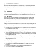
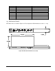
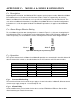
The Alarm Interface is a form C, insulated dry contact relay. It is energized in the N
O
A
LARM
state
and therefore defaults to the A
LARM
state in the event the PDU loses supply voltage. Figure A-2
shows the relay connections and terminal designators.
Maximum current rating is 1 A at 24 VDC or 0.5 A at 120 VAC.
NO
NC
COM
NO
NC
COM
No Alarm Alarm
Figure A-2: Alarm Interface relay
(47
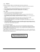
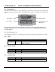
Pin-out for the Alarm Interface and DC Output connectors are shown in Figure A-3 and table below.
Figure A-3: Connector pin-out