
User guide

Bulletin II-102051-EN • Revision B November-2007 21
'( $!
#!
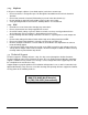
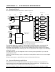
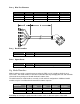
A functional block diagram of the PDU is shown in Figure A-1.
Summary
Alarm
Ctrl
DC+
GND
GND
DC-
Input
Pwr
Monitor
Input OK
DC/DC
Conv
DC2 OK
Voltage
Reg
Current Mon
and
Protection
Voltage
Reg
Current Mon
and
Protection
Voltage
Reg
Current Mon
and
Protection
Voltage
Reg
Current Mon
and
Protection
Voltage
Reg
Current Mon
and
Protection
Voltage
Reg
Current Mon
and
Protection
TMA Alarm x 6
DC Output
Power
TMA 1
TMA 2
TMA 3
TMA 4
TMA 5
TMA 6
Microprocessor
DC Output
Enable/Disable
High/Low Current
Mode Select
NC
Common
NO
Alarm
Interface
6 inputs
6 inputs
On/Off
TMA Alarm
Enable/Disable
6 inputs
6 outputs
Figure A-1: PDU Block Diagram
The input DC voltage (20 – 60 VDC) is converted to an intermediate voltage level by the DC/DC
converter. The intermediate voltage bus is then split into 6 output channels. Each channel is
individually regulated down to +12 VDC. A current monitoring circuit at the output of each voltage
regulator provides TMA alarm monitoring and short circuit protection. Each output can be individually
enabled or disabled.
The TMA alarm lines are OR-ed together to form a summary alarm signal which is presented for
monitoring by the BTS.
High/Low current alarm range can be selected by a shunting block to match the current consumption
of the TMA.
All inputs and outputs are protected from surges and electrostatic discharge.
('"
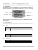
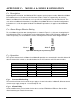
The PDU measures the current delivered from each output and compares it to a programmed
normal range of current consumption which depends on the selected mode. The Multimode PDU
supports multiple modes selectable by the Alarm Range Selector.
Current consumption below or above the normal range will result in alarm if alarming is enabled.