
User guide

18 November-2007 Bulletin II-102051-EN • Revision B
indications will clear once the problem is corrected.
" 5.55,,
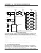
Each output is individually monitored. With associated TMA Alarm DIP switch E
NABLED
, current
consumption outside the selected range is considered a fault condition. Once a persistent fault
condition has existed on the same output for 5 s, the associated TMA Alarm LED turns R
ED
and the
Alarm Interface goes into the A
LARM
state. The Alarm Interface will return to the N
O
A
LARM
state
after 1 s once the problem is corrected. As a means to facilitate troubleshooting of intermittent
problems, the TMA Alarm LED will be latched and remain R
ED
until reset by the user.
An output with its DC Output DIP switch D
ISABLED
will supply no current. With the associated TMA
Alarm DIP switch E
NABLED
, this is a fault condition resulting in alarm indication.
While the Alarm Interface is in the A
LARM
state, any additional fault conditions will be immediately
indicated by the LEDs without a 5 s delay.
" ,:,6
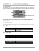
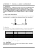
The Alarm Interface relay has two states. In the N
O
A
LARM
state, the relay is energized and indicates
trouble-free operation. The A
LARM
state (de-energized relay) is entered to indicate the presence of
any fault condition. A fault condition on a TMA output is ignored when the associated TMA Alarm
DIP switch is set to D
ISABLE
. When the PDU is turned off, the Alarm Interface defaults to the A
LARM
state.
// '"
"" 5.5,:
To reset a TMA output alarm indicated by a R
ED
TMA Alarm LED, flip the associated TMA Alarm
DIP switch up to D
ISABLE
. The LED will turn D
ARK
. Flip the switch down to re-E
NABLE
current
monitoring. If a fault is present, the LED will again turn R
ED
.
"" ,:
Turn the PDU O
FF
to reset all alarms. After turning back O
N
, any present or recurring fault will re-
activate alarm indications.
/1 4!-
Turn the PDU O
FF
. All alarms and delays are reset. The Alarm Interface defaults to the A
LARM
state.