
User guide

Bulletin II-102051-EN • Revision B November-2007 17
"
Before operating, ensure all parts of the TMA system are installed and all connections completed.
Also refer to instructions provided with other equipment.
/ 4
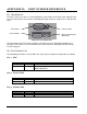
Turn the PDU O
N
. Verify that all front panel LEDs stay G
REEN
. Only LEDs for outputs with TMA
Alarm D
ISABLED
shall be D
ARK
. Observe the indications for 60 s to ensure they remain unchanged.
The TMA system is now operating. No further action is needed.
If short circuit conditions are present on outputs, the PDU may fail to start up. This is more likely to
occur with supply voltage in the lower part of the 20 – 60 VDC range. When failing, the PDU will
repeat the start-up sequence indefinitely, visible as the front panel LEDs keep flashing on and off.
Troubleshoot and correct the short circuit conditions per Section 7.
/ 5' '
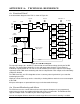
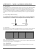
The PDU provides six independent regulated-voltage outputs. The nominal output voltage is +12
VDC with minimal variation across the operating temperature range and output currents up to 400
mA per output (2.2 A total maximum, all outputs).
/ ('
Output current is individually monitored for each output. Normal current is any current within the
range determined by the setting of the Alarm Range Selector. Current below or above this range is
considered a fault and will result in alarm indication.
/ (
Each TMA output is individually protected from over-current and short circuit conditions. Current in
excess of 400 mA on any output will cause the output to go into S
HORT
C
IRCUIT
P
ROTECTION
state.
The output voltage is then turned off, the TMA Alarm LED turns R
ED
, and the Alarm Interface goes
into the A
LARM
state. After a brief interval, the PDU will attempt to re-apply the output voltage.
Periodic attempts will continue until the over-current condition is cleared. At that time, the output
automatically resumes operation and the Alarm Interface goes into the N
O
A
LARM
state. The TMA
Alarm LED remains R
ED
until reset by the user.
Up to two outputs can be in the S
HORT
C
IRCUIT
P
ROTECTION
state while remaining outputs continue
operating. If more than two outputs experience simultaneous over-current conditions, DC/DC
converter protection may be activated, affecting the operation of all outputs.
/. "
" 5..-A4
The supply voltage is internally monitored. Voltage outside the acceptable range will result in the
Input OK LED turning D
ARK
and the Alarm Interface going into the A
LARM
state. The indications will
clear once the problem is corrected.
" 7*,,
The operation of the internal DC/DC converter is monitored. Malfunction, overload, or other problem
will result in the DC2 OK LED turning D
ARK
and the Alarm Interface going into the A
LARM
state. The