
User guide


16 November-2007 Bulletin II-102051-EN • Revision B
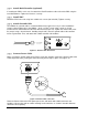
• For all outputs where DC Output DIP switches are E
NABLED
and TMA Alarm DIP switches are
E
NABLED
, the TMA Alarm LED is initially G
REEN
and turns R
ED
in 5 s.
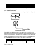
• For all outputs where TMA Alarm DIP switches are D
ISABLED
, the TMA Alarm LED stays D
ARK
.
• Ensure at least one TMA Alarm DIP switch is E
NABLED
and a TMA Alarm LED is lit R
ED
.
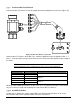
• The Alarm Interface relay indicates A
LARM
.
• Flip all TMA Alarm DIP switches up to D
ISABLE
.
• The Alarm Interface relay indicates N
O
A
LARM
.
• Restore all TMA Alarm DIP switches to their designated positions.
• Turn the PDU O
FF
.
*5
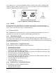
If the Functional Test was passed, proceed to finish the installation per Section 5.3.9. If any
problems were encountered, troubleshoot (see Section 7), and then redo the test.