
User guide


Bulletin II-102051-EN • Revision B November-2007 15
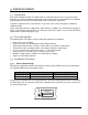
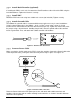
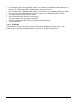
For all outputs in use, set the DC Output DIP switches to E
NABLE
(up) and the TMA Alarm DIP
switches to E
NABLE
(down). See Figure 17. For any unused outputs, set the corresponding DC
Output and TMA Alarm DIP switches to D
ISABLE
.
Enable
DC Output
Enable
Alarm
Figure 17: TMA Alarm and DC Output DIP switches
& ++8
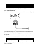
Check all connections and settings to ensure they are correct and secure. After passing the
Functional Test (see Section 5.4), dress and tie the cables making sure they are not exposed to
excess strain, crush, abrasion, heat, or accidental damage.
. #0
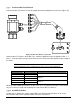
After completing the installation procedure, verify the installation by performing these tests. The
Functional Test can be done also prior to installing TMAs and/or Bias Tees.
86=-:
The PDU will be fully functional only once all parts of the TMA system are installed and all
connections made (complete system). To check the PDU installation before TMAs and/or Bias Tees
are installed (incomplete system), ensure the Bias Tee Harness SMA connectors are left unattached
during the Functional Test.
,,:@:.-:
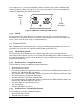
Turn the PDU O
N
. Verify the following front panel indications:
• Input OK LED stays G
REEN
• DC2 OK LED stays G
REEN
• For all outputs where DC Output DIP switches are E
NABLED
and TMA Alarm DIP switches are
E
NABLED
, the TMA Alarm LED stays G
REEN
.
• For all outputs where TMA Alarm DIP switches are D
ISABLED
, the TMA Alarm LED stays D
ARK
.
• The Alarm Interface relay indicates N
O
A
LARM
.
• Disconnect the Bias Tee Harness from the PDU.
• For all outputs where DC Output DIP switches are E
NABLED
and TMA Alarm DIP switches are
E
NABLED
, the TMA Alarm LED turns R
ED
in 5 s.
• The Alarm Interface relay indicates A
LARM
.
• Turn the PDU O
FF
.
• Reconnect the Bias Tee Harness.
,,:@6:.-:
Turn the PDU O
N
. Verify the following indications:
• Input OK LED stays G
REEN
• DC2 OK LED stays G
REEN