
User guide


8 November-2007 Bulletin II-102051-EN • Revision B
.59!
G
REEN
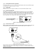
light indicates supply voltage is within specified range. D
ARK
otherwise.
9!
G
REEN
light indicates internal voltage is within specified range. A D
ARK
LED may indicate PDU
malfunction or short circuits present at more than two outputs.
" ,:!
G
REEN
light indicates voltage and current is within normal range for each output.
R
ED
light indicates a fault condition, i.e., current is outside normal range (including when the output
is disabled). The R
ED
light is latched and the indication will persist until reset by the user.
A D
ARK
LED indicates current monitoring is D
ISABLED
.
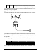
,:,66,
The Alarm Cable is connected here and routed to the BTS EAI. A summary A
LARM
state is indicated
if the PDU or any output is in a fault condition. The indication is automatically reset upon clearing the
fault condition. With no supply power to the PDU, the default indication is the A
LARM
state. An
insulated relay is used as the Alarm Interface.
; ,:3+68
Flip down to E
NABLE
current monitoring for each output. Flip up to D
ISABLE
. When D
ISABLED
, the
associated LED is D
ARK
, a latched R
ED
light is reset, and the Alarm Interface ignores the output.
& 5.53+68
Flip up to E
NABLE
and turn on voltage for each output. Flip down to D
ISABLE
. When D
ISABLED
, no
voltage is present on the output. If current monitoring is E
NABLED
, the LED and Alarm Interface
indicate a fault condition.
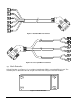
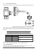
< 5.56,
The Bias Tee Harness is connected here and routed to up to six bias tees. Each of the six outputs is
individually monitored and protected. Nominal voltage is +12 VDC.
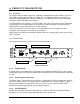
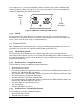
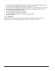
The rear panel control is illustrated in Figure 6.
LO CURRENT MODE
HI CURRENT MODE
ALARM RANGE
SELECTOR
LO CURRENT
HI CURRENT
Figure 6: Rear panel
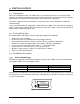
,:46,
With power switched off, a shunting block is positioned as shown to select LO
C
URRENT
or HI
C
URRENT
mode according to the type of TMA used. The factory default setting is LO
C
URRENT
mode.