
User guide


Bulletin II-102051-EN • Revision B November-2007 7
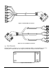
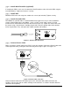
The PDU provides DC power conversion, regulation, and distribution to power TMAs at a cell site.
Each PDU can power up to six TMAs via six Bias Tees. Two different output current ranges are
supported for compatibility with a variety of TMA types. A shunting block on the rear panel allows
selection of the desired output current range.
The PDU monitors itself as well as each of the TMAs. The status of the PDU and each TMA output
is displayed by a set of LED indicators on the front panel. Alarm conditions are indicated by the
LEDs and also sent to the BTS EAI via the Alarm Interface.
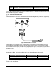
The PDU is housed in a 1 rack unit tall, 19” rack mountable enclosure, designed for indoor
installation. All connections are located on the front panel.
Supply power for the PDU is provided by the BTS. Positive or negative voltage in the range 20 – 60
VDC is accepted.
#
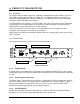
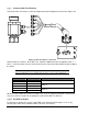
The front panel connections and controls are illustrated in Figure 5.
Figure 5: Front panel
%,5050
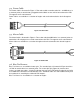
A ground cable can be attached here and routed to the equipment ground point. The cable should
be fitted with a 6mm (1/4”) diameter ring terminal. A 10 mm wrench is used to tighten the connection
securely.
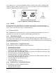
3,.56,
The Power Cable is connected here and routed to a supply point in the BTS providing 20 – 60 VDC,
positive or negative supply. The supply voltage is connected to Pin 1 (at left) and pin 4 (at right),
observing the polarity as marked on the panel. Pins 2 and 3 are not used. The Power Input is
floating (insulated from ground) and reverse polarity protected.
73+68
Controls the main power to the PDU. When power is turned off, delay timers and latched alarm
indications are reset, and the Alarm Interface defaults to the A
LARM
state.
Ground Stud Power Input Connector
LED Indicators DIP Switches