Installation and Operation User Guide
" 1.1 1.2 1.3 1.4 Purpose and Intended User of this Manual ........................................................................ 1 Scope ................................................................................................................................ 1 Glossary of Abbreviations.................................................................................................. 1 Reference Documents .............................................................................................
*++ $+ !" ,- # #" $% &" ! !" # $ % ! &' ' ( & ' &$ &) +)$ % ( % $ ' 1 $ iv ,' -'' $ ) '( $ ) $ ' * " * $ % % ' ( ' #$$ .
This manual provides a complete description of the Multimode Power Distribution Unit (PDU) along with installation and operating instructions for its use in general purpose applications. The intended user of this manual is an engineer or technician with adequate and specific experience in installing base transceiver station (BTS) and antenna line equipment such as base station antennas and tower mounted amplifiers (TMAs).
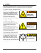
All operations relating to the installation of the PDU must be executed in accordance with industry approved safety standards and practices. The installer shall also follow the safety practices recommended by the BTS provider to insure that the BTS operation is not compromised. # $ %& The BTS, antenna line equipment, and the antennas generate high frequency electric and magnetic fields when in operation.
A typical TMA system consists of TMAs, Bias Tees, and PDU with accessories. For its function, the system also depends on the proper configuration of other antenna line equipment, including feeders and jumpers, surge arrestors, antennas, etc. This section provides single sector illustrations of several RF path configuration examples. While frequency bands vary and variations can occur, the examples provide guidance for many common situations.
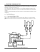
Bias Tees are installed on the antenna ports of one of the base stations. The diplexers must pass DC through that branch. DC blocks must be present in the other branch, either integral to the diplexers or in external devices as shown. # 1 + . /0 In Figure 2, dual-band, diplexed Andrew OneBase™ TMAs are used with shared feeders and shared antennas. OneBase™ diplexers at the BTS level incorporate DC redundancy circuitry, automatically routing the DC to the feeder and blocking the opposite branch.
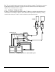
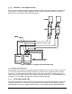
# 1 2 + . /0 Figure 3 shows a TMA system with Andrew OneBase™ TMAs and separate feeders for each band. The OneBase™ dual-band TMAs incorporate DC redundancy circuitry that allows DC supply for both bands to be provided to either BTS/Node-B port. Figure 3: OneBase™ non-diplexed dual-band TMA system ' , " A detailed connection diagram for a typical single-band TMA system is shown in Figure 4. The PDU receives DC input power from the BTS and outputs a summary alarm signal to the BTS.
To Antenna To Antenna ANT TMA GND To BTS RX/TX Bias Tee GND GND Feeder To BTS RX/TX GND Bias Tee Harness Black: 1 Tower Base Station Gray or Yellow: 2 White: 3 To Sector 2 Red: 4 Green: 5 To Sector 3 Blue: 6 PDU GND 2 1 Alarm Cable Blue: NO White: COM To EAI Brown: NC Power Cable White or 2: neg (-) To DC supply: ±20 to ±60 VDC Red or 1: pos (+) Figure 4: Single-band TMA system connection diagram 6 November-2007 Bulletin II-102051-EN • Revision B
The PDU provides DC power conversion, regulation, and distribution to power TMAs at a cell site. Each PDU can power up to six TMAs via six Bias Tees. Two different output current ranges are supported for compatibility with a variety of TMA types. A shunting block on the rear panel allows selection of the desired output current range. The PDU monitors itself as well as each of the TMAs. The status of the PDU and each TMA output is displayed by a set of LED indicators on the front panel.
.5 9! GREEN light indicates supply voltage is within specified range. DARK otherwise. 9! GREEN light indicates internal voltage is within specified range. A DARK LED may indicate PDU malfunction or short circuits present at more than two outputs. " ,: ! GREEN light indicates voltage and current is within normal range for each output. RED light indicates a fault condition, i.e., current is outside normal range (including when the output is disabled).
- ( The Power Cable is illustrated in Figure 7. Two color-coded or number-coded 18 – 24 AWG wires in a common jacket are attached to a pluggable terminal block on one end for connection to the PDU. The opposite end is unterminated. Power Cables are available in a selection of lengths and can be trimmed to the desired length on site. Figure 7: Power Cable . "( The Alarm Cable is illustrated in Figure 8.
Figure 9: Standard Bias Tee Harness Figure 10: Sector-split Bias Tee Harness 1 2)3 A Rack Extender (see Figure 11) is used when installing the PDU in a standard EIA 23” rack. The extender plate is attached to the left or right side of the PDU using the enclosed hardware.
!! . Select the installation location. The PDU installs in a standard 19” rack (or 23” rack using a Rack Extender) in a climate controlled environment. It can be mounted in any orientation. Ensure optimum airflow around the instrument for cool operation and maximum life expectancy. Inspect the equipment. Ensure that all items are present, of the correct description, and without evident damage. Locate connection points for supply power, alarm interface, and Bias Tees. Determine the routing of cables.
68 6= / 0 ,> . + ? If installing the PDU in a 23” rack, first attach the Rack Extender to either side of the PDU using the included hardware. Tighten the fasteners securely. Mount the PDU in the rack using four suitable rack screws (not included). Tighten securely. 68%, 5 0 The addition of a ground cable is recommended but may not be necessary in some installations.
% ) *, . % " = ' >$ 9 : ' "-" . :7 ;! < % = ' % &-" ' 9 ? . ?7 ;! < Use a dedicated circuit for the PDU if the BTS power panel is so equipped. Install a fuse or circuit breaker with a rating in the 1-5 A range. " 6 ,: Connect the Alarm Cable to the Alarm Interface connector and tighten the jackscrews (Figure 15). Figure 15: Alarm Cable connection Choose which relay terminals to use.
6 #+ $ , Connect the Bias Tee Harness to the DC Output connector and tighten the jackscrews (Figure 16). Figure 16: Bias Tee Harness connection Route the Bias Tee Harness to the Bias Tees, attach the SMA connectors and tighten to 0.8 – 1.1 Nm (7 – 10 in-lbs) torque using an 8 mm (5/16”) wrench. Refer to the table below for color coding of the cables. If TMA installation is not complete, leave the SMA connectors unattached until a Functional Test per Section 5.4 has been successfully completed. % #%/ .
For all outputs in use, set the DC Output DIP switches to ENABLE (up) and the TMA Alarm DIP switches to ENABLE (down). See Figure 17. For any unused outputs, set the corresponding DC Output and TMA Alarm DIP switches to DISABLE. Enable Alarm Enable DC Output Figure 17: TMA Alarm and DC Output DIP switches & + +8 Check all connections and settings to ensure they are correct and secure. After passing the Functional Test (see Section 5.
• • • • • • • • For all outputs where DC Output DIP switches are ENABLED and TMA Alarm DIP switches are ENABLED, the TMA Alarm LED is initially GREEN and turns RED in 5 s. For all outputs where TMA Alarm DIP switches are DISABLED, the TMA Alarm LED stays DARK. Ensure at least one TMA Alarm DIP switch is ENABLED and a TMA Alarm LED is lit RED. The Alarm Interface relay indicates ALARM. Flip all TMA Alarm DIP switches up to DISABLE. The Alarm Interface relay indicates NO ALARM.
" Before operating, ensure all parts of the TMA system are installed and all connections completed. Also refer to instructions provided with other equipment. / 4 Turn the PDU ON. Verify that all front panel LEDs stay GREEN. Only LEDs for outputs with TMA Alarm DISABLED shall be DARK. Observe the indications for 60 s to ensure they remain unchanged. The TMA system is now operating. No further action is needed. If short circuit conditions are present on outputs, the PDU may fail to start up.
indications will clear once the problem is corrected. " 5 .5 5,, Each output is individually monitored. With associated TMA Alarm DIP switch ENABLED, current consumption outside the selected range is considered a fault condition. Once a persistent fault condition has existed on the same output for 5 s, the associated TMA Alarm LED turns RED and the Alarm Interface goes into the ALARM state. The Alarm Interface will return to the NO ALARM state after 1 s once the problem is corrected.
#! $ % Because the PDU supplies and monitors the entire TMA system, all system components should be considered when troubleshooting. The TMA system can include TMA, Bias Tee, surge arrestor, diplexer (crossband coupler), and other devices in addition to RF and DC cables and connectors as well as the PDU itself. 1 " 5 + : , A digital instrument is preferred, capable of measuring DC voltage, current, and resistance.
+ . /, If DC passes through a diplexer (crossband coupler) at the base or tower top: • • • • • • • • • • • • 1 Ensure the device is designed to pass DC through the intended branch and in the intended direction. Ensure that (external or internal) DC blocking is present in the other branch(es). Do not attempt to supply DC from multiple sources to the same feeder. Verify operating bands of each branch if VSWR problems are encountered. Remember to reset alarms after changing any connections.
' # ( $ ! ! A functional block diagram of the PDU is shown in Figure A-1.
Andrew TMAs are equipped with internal fault monitoring and will raise or lower their current consumption as a means to signal a fault condition to the PDU. Abnormal current consumption can also result from other problems in the DC path from PDU to TMA. The table below summarizes the behavior of the PDU in the LO CURRENT and HI CURRENT modes: / % ! ( # ( $ % % % ' 3/ % ' ( *+ 12% ' ( *+ 5. 2 ? ./4 6.74 6A 5. .4 ? 2 .
5 . 2 A / 7 4 B . + *2 & $ #%/ ) .: ) : ) 2: ) A: ) /: ) 7: =! =! 3 & 3 3 3 3 3 3 ! PDU dimensions are shown in Figure A-4. The weight of the PDU without accessories is 1.1 kg.
' #( # , The PDU and its accessories are each identified by a part number and revision code, typically found on a label affixed to the item and/or its individual packaging. A label as in Figure B-1 is affixed to the PDU.
# #+ $ , 5 )7. ." . 7. ."2 7. ."24 7. ."A/ # !" 6= / " ., 5 , 3 & + // ./ . B/ 3 & 6 / / / / 0, 5 ).B?4 2 ?. # . !" #" .BD 2D .8 , )E ?.. !" #" $' % 1 % 8" Model numbers provide a convenient way to order the PDU as a kit, including a defined set of accessories. The model number is found on a label affixed to the packaging of the kit and should be referenced when placing an order with Andrew Customer Care.
' ( ( ) # ! Beginning with revision 02, the Multimode PDU supports special purpose modes MODE A and MODE B in addition to the LO CURRENT and HI CURRENT modes, which are supported by all revisions. MODE A and MODE B are intended for use in specific site configurations not described herein. The user will need additional information if using MODE A and MODE B in these intended configurations. Included here is a full description of Mode A and Mode B operation as it applies to the Multimode PDU.
)/ 2%4 )$ # $' - * &$ # +, ( 7 - 7 $% +, ,' ,' ,' -* '$ ( ,' ,' ( $ ' ' ! "# " $$" %&' - !. "&&'"%/$" $ # /6 , ' 6 $ # ' ( # ) - ( $ $$ .