
User's Manual
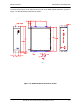
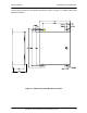
Table Of Contents
- GENERAL MANUAL INFORMATION
- PREPARATION FOR STORAGE OR SHIPMENT
- DESCRIPTION OF EQUIPMENT
- LOCATIONS AND DESCRIPTIONS OF MAJOR COMPONENTS
- EQUIPMENT CHARACTERISTICS
- INSTALLING THE RADIO EQUIPMENT
- INTERCONNECTIONS
- CABLE AND GROUND REQUIREMENTS
- COMPONENT JACK LOCATIONS
- INITIAL PREPARATION FOR USE
- RADIO APPLICATION CODE UPGRADE
- PN SPREADING CODE SELECTION
- ANTENNA AND CABLE INSTALLATION
- CONTROLS AND INDICATORS
- STARTUP AND SHUTDOWN PRODECURES
- OUTPUT POWER SETTINGS
- ANTENNA PLACEMENT
- FUNCTIONAL DESCRIPTION OF EQUIPMENT
- PREVENTIVE MAINTENANCE, INSPECTION, AND CLEANING
- TROUBLESHOOTING
- CORRECTIVE MAINTENANCE
- TEST PROCEDURES
- MDR TESTS
- BDR TESTS
- RADIO DATA PORT TO USER SUPPLIED EQUIPMENT INTERFACE
- PARTS LIST
- BASE DATA RADIO MECHANICAL OUTLINE
- DIAGNOSTIC MENU
- MDR DIAGNOSTIC LCP MENU
- LCP COMMANDS

385700-1006-006 DIAGNOSTIC LCP MENU
Document use is restricted to that described on cover 8-6
OS-9 SHELL BDR and MDR
This command is reserved for future use or internal unit testing. The ESCAPE key is
used to return the radio to its normal operating condition from this state.
SET RCS ADDRESS BDR
This command sets the BDR address. It is used in multiple BDR configurations. The
allowable range of address is 01
16
to FE
16
. A default address of 40
16
is preloaded into
the BDR upon power up initialization.
See the ICD for further information.
SSR STATUS REQUEST BDR and MDR
This command reads the current configuration data stored inside various modules
within the radio. It includes a display that indicates whether the data agrees with the
data originally written to the modules. The parameters currently supported are the
lower lock, lower, and upper thresholds, the Tx and Rx PN code, the Tx and Rx Data
Rates, and the current state of the Transmitter. All other parameters are for future
use.
STATUS REQUEST BDR and MDR
This command displays the current radio configuration as stored in the radio’s volatile
memory. The parameters currently supported are the lower lock, lower, and upper
thresholds, the Tx and Rx PN code, the Tx and Rx Data Rates, and the current state
of the Transmitter. All other parameters are for future use.
SHOW POLL COUNTERS BDR
This command displays a group of communication counters that monitor the polling
activity between the BDR and MDR and special flags used for internal radio code
debugging. The counter types currently supported are the number of poll requests
input to the BDR, the number of frames transmitted from the BDR controller to the
radio RF transmitter, the number of valid poll responses received from the MDR, the
total number of frames received from the radio RF port at the BDR controller, and the
number of poll request retransmission attempts.
CLEAR POLL COUNTERS
This command zeroes a group of communication counters that monitor the polling
activity between the BDR and MDR.
READ TRACK/AGC VALUES BDR and MDR
This command is reserved for future use or internal unit testing.
SET dBM OUTPUT LEVEL BDR and MDR
This command is used to set the transmitter output power level of the radio. The
range of listed output levels may be greater than the specifications of the radio. When
using this command, the user must set the output level such that compliance with FCC
output level requirements are maintained. The output resolution is in 1 dB increments.
CHANGE dBM/DAC VALUES BDR and MDR
This command is reserved for factory calibration or internal unit testing. The
command, Set dBM Output Level, is used to enter the PA control voltages
corresponding to an RF output levels. After entering the voltage/ RF levels, the user