
User's Manual
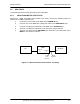

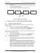
Table Of Contents
- GENERAL MANUAL INFORMATION
- PREPARATION FOR STORAGE OR SHIPMENT
- DESCRIPTION OF EQUIPMENT
- LOCATIONS AND DESCRIPTIONS OF MAJOR COMPONENTS
- EQUIPMENT CHARACTERISTICS
- INSTALLING THE RADIO EQUIPMENT
- INTERCONNECTIONS
- CABLE AND GROUND REQUIREMENTS
- COMPONENT JACK LOCATIONS
- INITIAL PREPARATION FOR USE
- RADIO APPLICATION CODE UPGRADE
- PN SPREADING CODE SELECTION
- ANTENNA AND CABLE INSTALLATION
- CONTROLS AND INDICATORS
- STARTUP AND SHUTDOWN PRODECURES
- OUTPUT POWER SETTINGS
- ANTENNA PLACEMENT
- FUNCTIONAL DESCRIPTION OF EQUIPMENT
- PREVENTIVE MAINTENANCE, INSPECTION, AND CLEANING
- TROUBLESHOOTING
- CORRECTIVE MAINTENANCE
- TEST PROCEDURES
- MDR TESTS
- BDR TESTS
- RADIO DATA PORT TO USER SUPPLIED EQUIPMENT INTERFACE
- PARTS LIST
- BASE DATA RADIO MECHANICAL OUTLINE
- DIAGNOSTIC MENU
- MDR DIAGNOSTIC LCP MENU
- LCP COMMANDS

385700-1006-006 MAINTENANCE AND TROUBLESHOOTING
Document use is restricted to that described on cover 5-17
further information.
5.7.3 RS-232 DATA 2 PORT SETUP
Referring to MDR Transmitter Fault Isolation Test Setup, perform the following actions to
prepare the MDR
1. Connect the power cable to the MDR at the
POWER IN
port.
2. Connect a PC to the MDR with a diagnostic cable at the
DIAGNOSTIC
port.
3. Connect a 20 dB power attenuator to the MDR at the
ANTENNA
port.
4. Connect a computer serial port to the MDR
Data Port 2
using adapters as
needed. Setup the computer to run ProComm™ (or other Terminal
Communication Program
5.7.4 RS-232 DATA 2 PORT TEST
1. From the MDR LCP terminal select command #28 (Status Request) to verify
that the MDR
Data Port 2
parameters match those of the user supplied
equipment. If the parameters are not the same, configure the MDR per section
rt Configuration (Optional)
3. After verifying that
Data Port 1
is correctly attached to the user supplied
equipment , the user supplied equipment should be configured to send a
message to the MDR. If the message appears on the computer screen,
Data
Port 2
is operational. The user supplied equipment and cabling connected to
Data Port 2
should be checked for proper configuration and operation. If the
message does not appear on the computer screen and the cable is correctly
configured the radio should be replaced. Contact Andrew for further
information.