
User's Manual
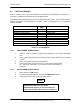
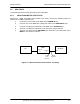

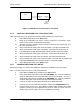
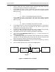
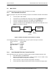
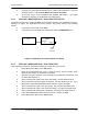
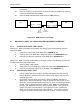
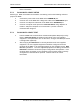
Table Of Contents
- GENERAL MANUAL INFORMATION
- PREPARATION FOR STORAGE OR SHIPMENT
- DESCRIPTION OF EQUIPMENT
- LOCATIONS AND DESCRIPTIONS OF MAJOR COMPONENTS
- EQUIPMENT CHARACTERISTICS
- INSTALLING THE RADIO EQUIPMENT
- INTERCONNECTIONS
- CABLE AND GROUND REQUIREMENTS
- COMPONENT JACK LOCATIONS
- INITIAL PREPARATION FOR USE
- RADIO APPLICATION CODE UPGRADE
- PN SPREADING CODE SELECTION
- ANTENNA AND CABLE INSTALLATION
- CONTROLS AND INDICATORS
- STARTUP AND SHUTDOWN PRODECURES
- OUTPUT POWER SETTINGS
- ANTENNA PLACEMENT
- FUNCTIONAL DESCRIPTION OF EQUIPMENT
- PREVENTIVE MAINTENANCE, INSPECTION, AND CLEANING
- TROUBLESHOOTING
- CORRECTIVE MAINTENANCE
- TEST PROCEDURES
- MDR TESTS
- BDR TESTS
- RADIO DATA PORT TO USER SUPPLIED EQUIPMENT INTERFACE
- PARTS LIST
- BASE DATA RADIO MECHANICAL OUTLINE
- DIAGNOSTIC MENU
- MDR DIAGNOSTIC LCP MENU
- LCP COMMANDS

385700-1006-006 MAINTENANCE AND TROUBLESHOOTING
Document use is restricted to that described on cover 5-16
information.
15. From the respective LCP terminals, shut off the radio transmitters by selecting
command #15 (Disable Transmitter).
16. Place the MDR and BDR power switches to the
OFF
positions.
Figure 5-10 BDR Receiver Test Setup
5.7 RADIO DATA PORT TO USER SUPPLIED EQUIPMENT INTERFACE
5.7.1 EIA-530 DATA PORT TEST SETUP
Referring to MDR Transmitter Fault Isolation Test Setup, perform the following actions to
prepare the MDR
1. Connect the power cable to the MDR at the
POWER IN
port.
2. Connect a PC to the MDR with a diagnostic cable at the
DIAGNOSTIC
port.
3. Connect a 20 dB power attenuator to the MDR at the
ANTENNA
port.
Referring to BDR Transmitter Fault Isolation Test Setup, perform the following to prepare for
the BDR transmitter fault isolation test:
1. Connect power cable to BDR.
2. Connect the PC to the BDR with a diagnostic cable at the
DIAGNOSTIC
port.
3. Connect a 20 dB power attenuator to the BDR at the
ANTENNA
port.
5.7.2 EIA 530 DATA PORT TEST
1. From the BDR LCP terminal select command #28 (Status Request) to verify
that the BDR RCS address matches the address in the frames from the user
supplied equipment.
2. Remove the external cables from DATA 1 (Base and Mobile) and DATA 2
(Base) ports. With an oscilloscope, verify the presence of the 64 KHz TX and
RX clocks and the RX data signals at the DATA 1 (Base and Mobile) and DATA
2 ports. Refer to BDR Data 1 Port Cable Pin-outs, BDR Data 2 Port Cable
Pin-outs, and MDR Data 1 Port Pin-outs for pinout details. If the signals are
inactive, the radio is not operational. If the signals are active, reattach the
cables and verify the integrity of the cable assembly. If the cable is correctly
configured and radio communication still does not occur, contact Andrew for
PC
BDR
Diagnostic
J4
Antenna
J5
20 dB
Power
Attenuator
20 dB
Attenuator
MDR
Antenna
J5
Diagnostic
J4
PC