
User's Manual
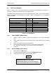
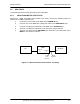

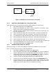
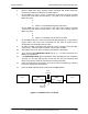
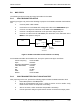
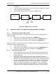
Table Of Contents
- GENERAL MANUAL INFORMATION
- PREPARATION FOR STORAGE OR SHIPMENT
- DESCRIPTION OF EQUIPMENT
- LOCATIONS AND DESCRIPTIONS OF MAJOR COMPONENTS
- EQUIPMENT CHARACTERISTICS
- INSTALLING THE RADIO EQUIPMENT
- INTERCONNECTIONS
- CABLE AND GROUND REQUIREMENTS
- COMPONENT JACK LOCATIONS
- INITIAL PREPARATION FOR USE
- RADIO APPLICATION CODE UPGRADE
- PN SPREADING CODE SELECTION
- ANTENNA AND CABLE INSTALLATION
- CONTROLS AND INDICATORS
- STARTUP AND SHUTDOWN PRODECURES
- OUTPUT POWER SETTINGS
- ANTENNA PLACEMENT
- FUNCTIONAL DESCRIPTION OF EQUIPMENT
- PREVENTIVE MAINTENANCE, INSPECTION, AND CLEANING
- TROUBLESHOOTING
- CORRECTIVE MAINTENANCE
- TEST PROCEDURES
- MDR TESTS
- BDR TESTS
- RADIO DATA PORT TO USER SUPPLIED EQUIPMENT INTERFACE
- PARTS LIST
- BASE DATA RADIO MECHANICAL OUTLINE
- DIAGNOSTIC MENU
- MDR DIAGNOSTIC LCP MENU
- LCP COMMANDS

385700-1006-006 MAINTENANCE AND TROUBLESHOOTING
Document use is restricted to that described on cover 5-10
For this test, set up the spectrum analyzer as follows:
• Center Frequency = 2467.84 MHz
• Span = 60 MHz
• Resolution Bandwidth = 100 KHz
• Video Bandwidth = 300 Hz
• Atten = 10 dB
• Ref = 0 dBm
• SWP = Auto
• Marker = 2467.84 MHz
5.5.2 MDR TRANSMITTER FAULT ISOLATION TEST
After preparing for the test, perform the following to isolate the transmitter fault:
1. Place the MDR power switch to the ON position.
2. Bring up the Diagnostic LCP screen. Refer to section 2.5.2 for details. Verify
that the radio self test is completed successfully.
3. At the PC’s LCP menu, select command #16 (Enable Transmitter).
4. Select command #33 (Set dBm output level.) Set output level to 24 dBm.
5. Use the spectrum analyzer’s peak search function to monitor the output power.
6. Compare the output spectrum peak level to MDR Output Spectrum. The level
should be within ±3 dB of the level shown in
Error! Reference source not
found.
.
7. At the LCP menu, select command #15 (Disable Transmitter). The signal
should be down a minimum of 40 dB from the enable levels.
5.5.3 MDR ONLY RECEIVER FAULT ISOLATION TEST SETUP
Refer to MDR Receiver Fault Isolation Test Setup. Preparation for the test to isolate the
MDR receiver fault is similar to the transmitter test setup. The 20 dB attenuation may remain
on the
ANTENNA
port for the remainder of this test. Referring to MDR Receiver Fault
Isolation Test Setup, perform the following actions:
1. Connect the power cable to the MDR at INPUT 28 VDC.
2. Connect the PC to the MDR with a diagnostic cable at the
DIAGNOSTIC
port.