
User's Manual


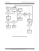
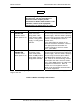


Table Of Contents
- GENERAL MANUAL INFORMATION
- PREPARATION FOR STORAGE OR SHIPMENT
- DESCRIPTION OF EQUIPMENT
- LOCATIONS AND DESCRIPTIONS OF MAJOR COMPONENTS
- EQUIPMENT CHARACTERISTICS
- INSTALLING THE RADIO EQUIPMENT
- INTERCONNECTIONS
- CABLE AND GROUND REQUIREMENTS
- COMPONENT JACK LOCATIONS
- INITIAL PREPARATION FOR USE
- RADIO APPLICATION CODE UPGRADE
- PN SPREADING CODE SELECTION
- ANTENNA AND CABLE INSTALLATION
- CONTROLS AND INDICATORS
- STARTUP AND SHUTDOWN PRODECURES
- OUTPUT POWER SETTINGS
- ANTENNA PLACEMENT
- FUNCTIONAL DESCRIPTION OF EQUIPMENT
- PREVENTIVE MAINTENANCE, INSPECTION, AND CLEANING
- TROUBLESHOOTING
- CORRECTIVE MAINTENANCE
- TEST PROCEDURES
- MDR TESTS
- BDR TESTS
- RADIO DATA PORT TO USER SUPPLIED EQUIPMENT INTERFACE
- PARTS LIST
- BASE DATA RADIO MECHANICAL OUTLINE
- DIAGNOSTIC MENU
- MDR DIAGNOSTIC LCP MENU
- LCP COMMANDS

385700-1006-006 MAINTENANCE AND TROUBLESHOOTING
Document use is restricted to that described on cover 5-2
Observe
Power on
Indicator
Is Power on
Indicator
Illuminated?
Check Input
Power Cabling
Is Cabling
Properly
Connected?
Properly
Connect
Cabling
Continue MDR
Troubleshooting
Process
Is Cabling
Damaged?
Replace
Cabling
Check Power
Switch
Is Power
Switch in On
Position?
Place Power
Switch to On
Position
Check Input 28
VDC Connector
for nominal 28
VDC
Is 28 VDC
Present?
Check
External
Power Supply
Replace MDR
N
N
N
N
Y
Y
Y
Y
N
Y
Figure 5-1 MDR Fault Isolation Flow Diagram