
User's Manual


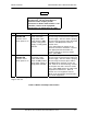


Table Of Contents
- GENERAL MANUAL INFORMATION
- PREPARATION FOR STORAGE OR SHIPMENT
- DESCRIPTION OF EQUIPMENT
- LOCATIONS AND DESCRIPTIONS OF MAJOR COMPONENTS
- EQUIPMENT CHARACTERISTICS
- INSTALLING THE RADIO EQUIPMENT
- INTERCONNECTIONS
- CABLE AND GROUND REQUIREMENTS
- COMPONENT JACK LOCATIONS
- INITIAL PREPARATION FOR USE
- RADIO APPLICATION CODE UPGRADE
- PN SPREADING CODE SELECTION
- ANTENNA AND CABLE INSTALLATION
- CONTROLS AND INDICATORS
- STARTUP AND SHUTDOWN PRODECURES
- OUTPUT POWER SETTINGS
- ANTENNA PLACEMENT
- FUNCTIONAL DESCRIPTION OF EQUIPMENT
- PREVENTIVE MAINTENANCE, INSPECTION, AND CLEANING
- TROUBLESHOOTING
- CORRECTIVE MAINTENANCE
- TEST PROCEDURES
- MDR TESTS
- BDR TESTS
- RADIO DATA PORT TO USER SUPPLIED EQUIPMENT INTERFACE
- PARTS LIST
- BASE DATA RADIO MECHANICAL OUTLINE
- DIAGNOSTIC MENU
- MDR DIAGNOSTIC LCP MENU
- LCP COMMANDS

385700-1006-006 OPERATIONS
Document use is restricted to that described on cover 4-6
4.1.5 ANTENNA SWITCHING CONTROLS
The MDR Data 2 Port includes 3 signals, see MDR Data 2 Port Pin-outs, that can provide 20
ma of drive current. The current based signals, ANT0-ANT2, can be connected to a user
supplied external switch that controls a multiple antenna configuration that is connected to the
MDR. The return current path signals, SIGA GND, are tied together inside the radio. The
software control of the antenna select lines is defined in the Radio Communication System
Interface Control Document.
The MDR Data 2 Port also provides a power and power return path, see MDR Data 2 Port
Pin-outs, to the user. The power signal, RADIO PWR, is taken directly from the user supplied
input source. The electrical path is made with 22-gauge wire. The user is responsible to
insure that (1) the current draw is within the limits that this gauge wire can support and (2) that
the user supplied DC power source can supply this current load as well as the current load
required by the MDR.